// Technical libraryXeon NC / Engineering resources
Design
guidelines.
The details shape the part.
Make the details work. Practical rules for CAD files, material selection, dimensions, tolerances, and production-ready parts.
Start with a question
In the spotlight.
Explore articles ↗All guidelines.
69 guidelines
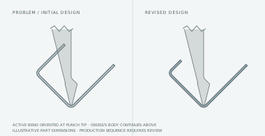
Bending / Original CAD examples
Better bends start in the model.
Explore eight bending checks with real tool profiles and Onshape comparisons. Inspect tool access, then see why an overbend opens to the finished angle after springback.
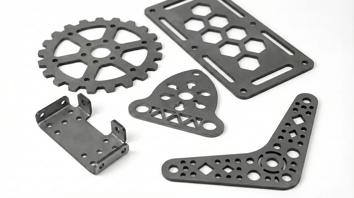
Materials / Grade selection
Carbon steel. The grade changes the part.
Compare the steel materials in the Xeon NC catalog: A1008, galvanized steel, A36 / A1011, Grade 50, Corten, AR500, and spring steel. Explore their tradeoffs in an interactive radar viewer.
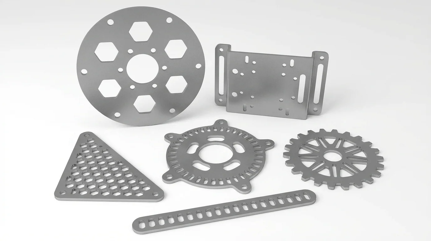
Materials / Alloy selection
Aluminum. The alloy changes the part.
Compare aluminum alloys and tempers with an interactive radar viewer. Explore 1100, 3003, 5052, 6061, 2024, and 7075 through strength, forming, machining, welding, and corrosion.
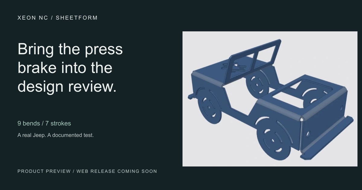
Engineering tools / Preview
Bring the press brake into the design review.
Use the Xeon Jeep to follow SheetForm from STEP import to tooling, sequence simulation, and the warnings that guide the next revision.
Materials / Grade selection
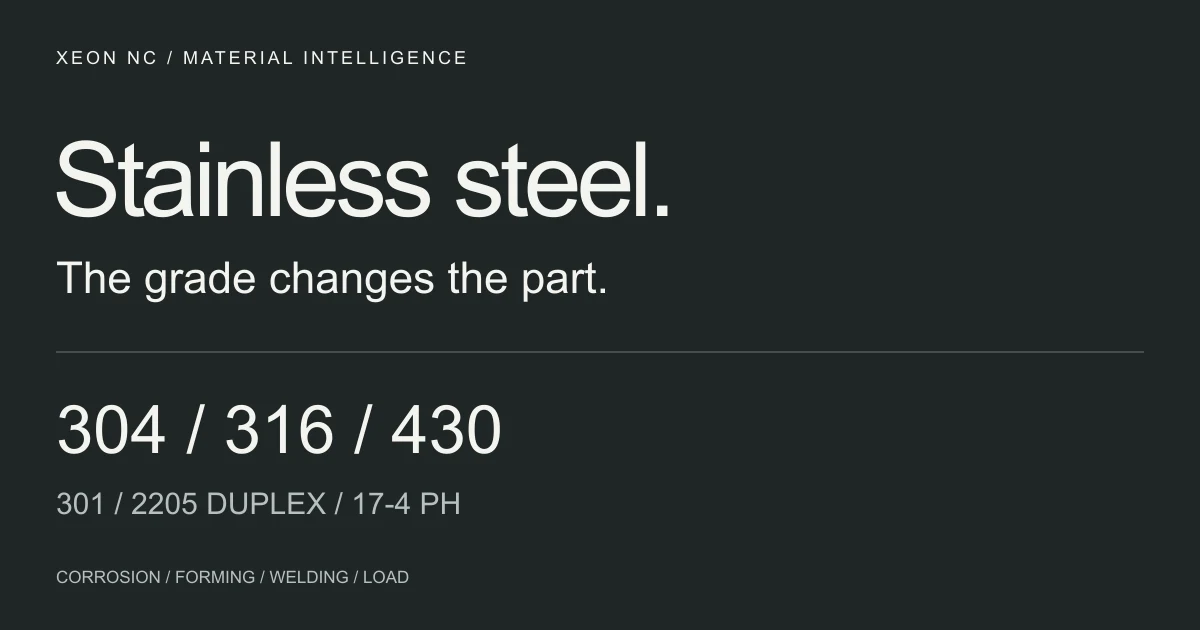
Stainless steel. The grade changes the part.
Understand stainless steel grades through corrosion, forming, welding, and load. Compare 304L, 316L, 430, 301, 2205 duplex, and 17-4 PH before specifying sheet metal.
Design / Assembly engineering
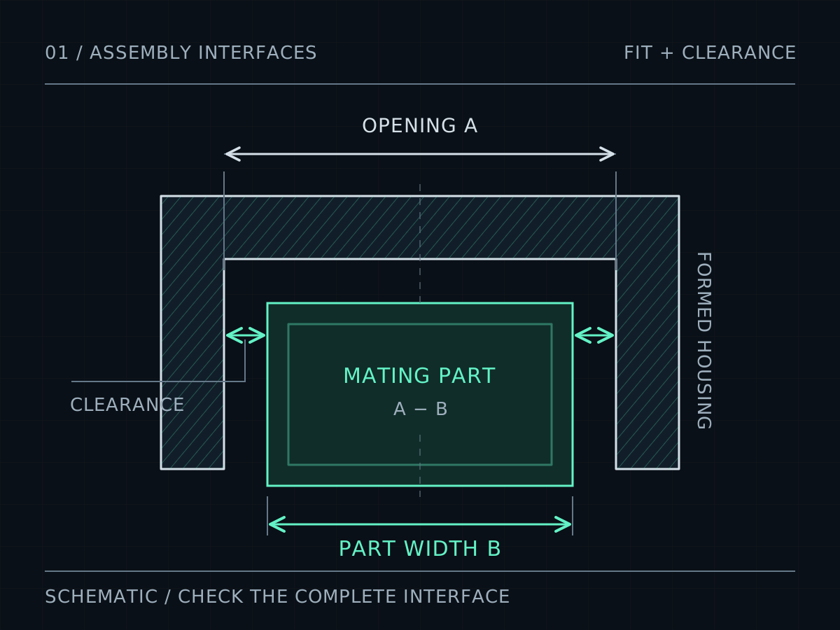
Why Good Parts Don’t Fit: Sheet Metal Tolerance Stacks
Calculate assembly clearance across formed sheet metal, mating parts, and coatings. A worked tolerance stack, interactive calculator, and inspection checklist.
Design / Assembly engineering
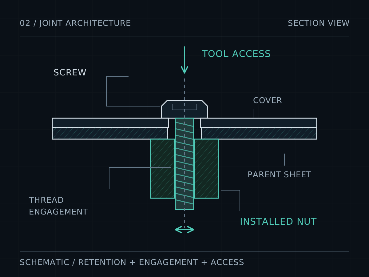
Threads in Thin Sheet: Choose the Joint Before the Hole
Choose tapped sheet, self-clinching nuts, rivet nuts, or through-bolts by load path, tool access, service requirements, and finishing sequence.
Design / Assembly engineering
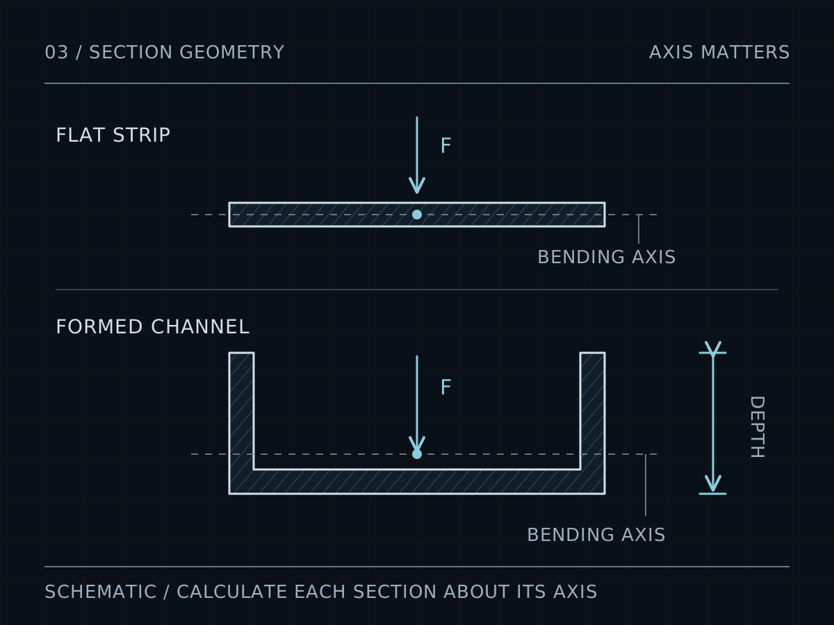
Stiffness Comes from Shape: Designing Lighter Sheet Metal Parts
Design sheet metal for stiffness with clear load cases, section depth, return flanges, shorter spans, and a worked cantilever calculation.
Design / Assembly engineering
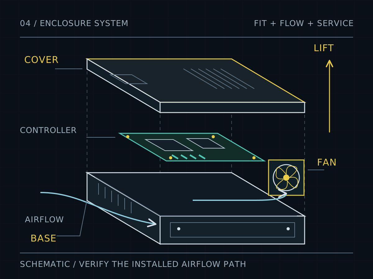
The Enclosure Is a System: Fit, Airflow, and Service Access
Design sheet metal enclosures around mating datums, coating allowance, cooling paths, cable access, and service sequences. Includes a practical release review.
Design / Assembly engineering
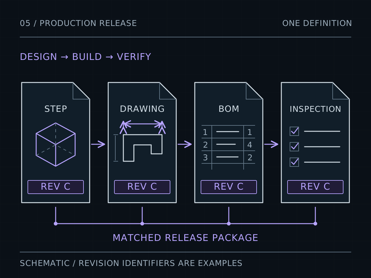
From Prototype to Repeat Order: Build a Production Release That Holds Up
Turn a successful sheet metal prototype into a controlled repeat order with a release package, revision rules, inspection plan, and downloadable register.
Materials / Manufacturing Insights
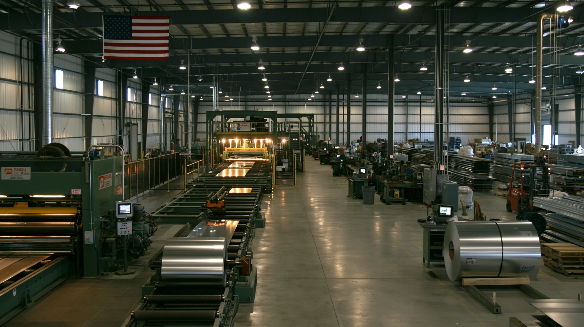
Standard Sheet Metal Sizes: Design Around the Sheet
Compare stock formats, understand custom cut-to-length costs, and see how flat-pattern dimensions change material yield.
Design / Manufacturing Insights
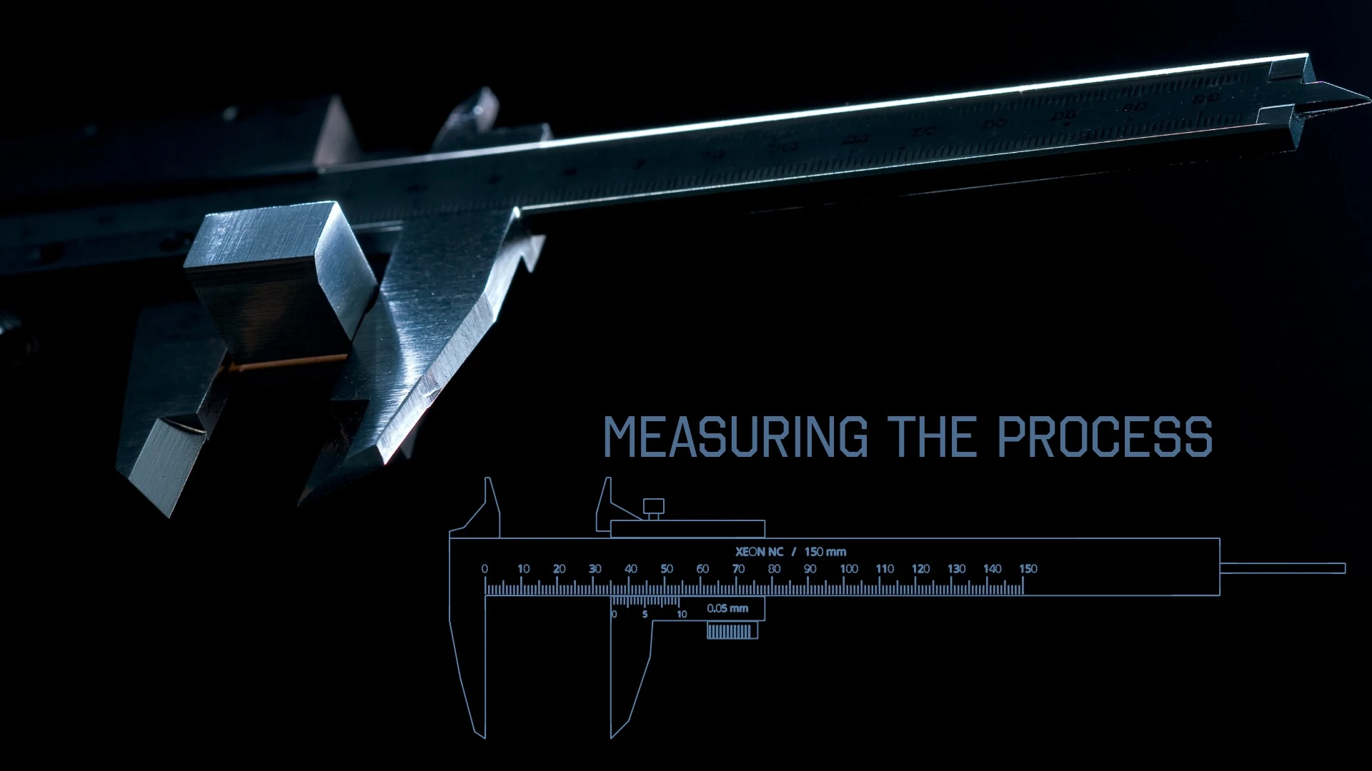
Sheet Metal Tolerances: CNC & 3D Printing Compared
Understand flat and formed tolerances, see how angle moves a mounting point, and specify a fit each process can verify.
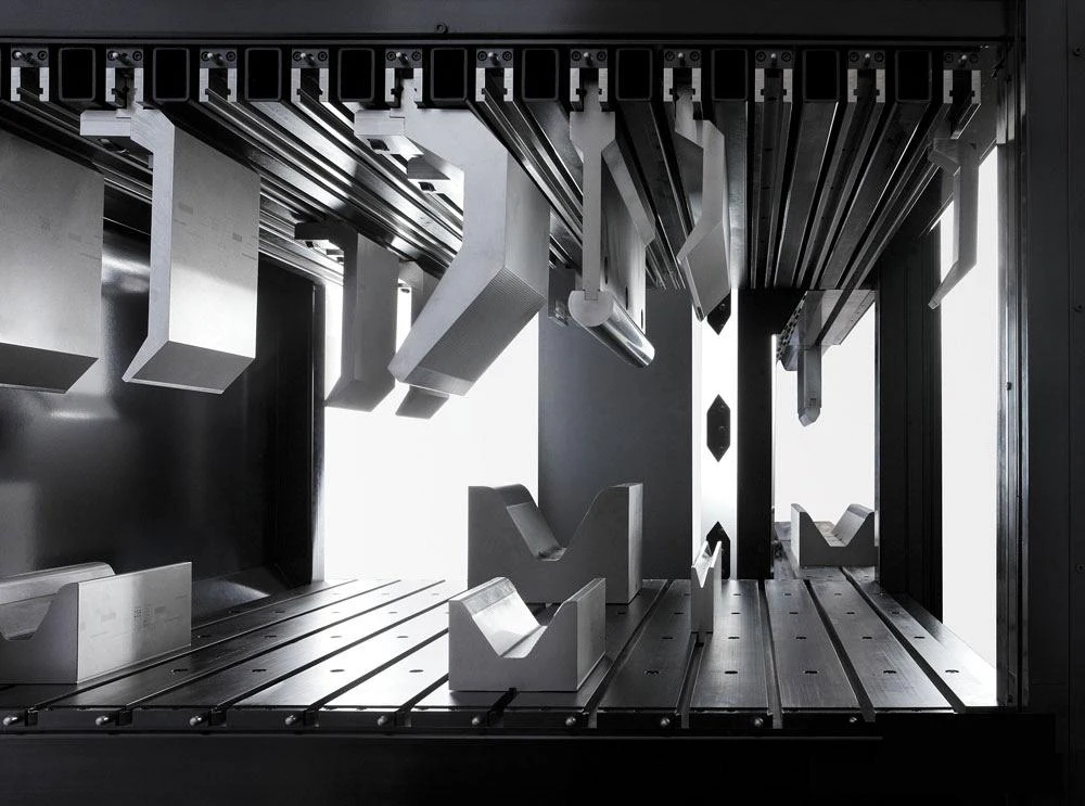
Bending / Design Calculator
How Tall Can Your Box Be?
Compare Xeon’s five punches in a live 2D section. Estimate maximum inside box height, understand holder clearance, and check an opposing wall against the tool.
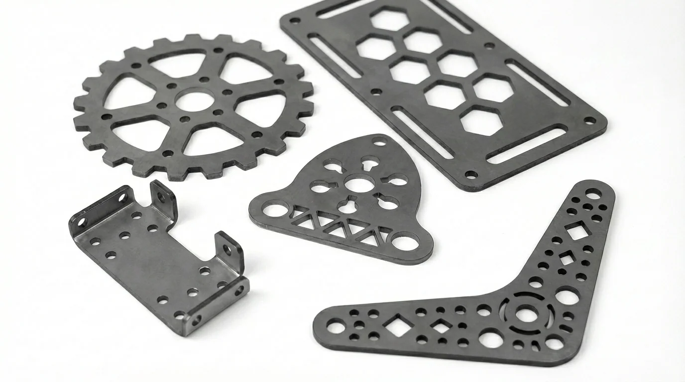
Materials / Process
Hot-Rolled vs. Cold-Rolled vs. HR P&O Steel: How Each Is Made
One slab, three products. See what the hot strip mill, the pickling line, and the cold mill each do to the steel, then choose between the A36 / A1011 and A1008 options Xeon stocks.
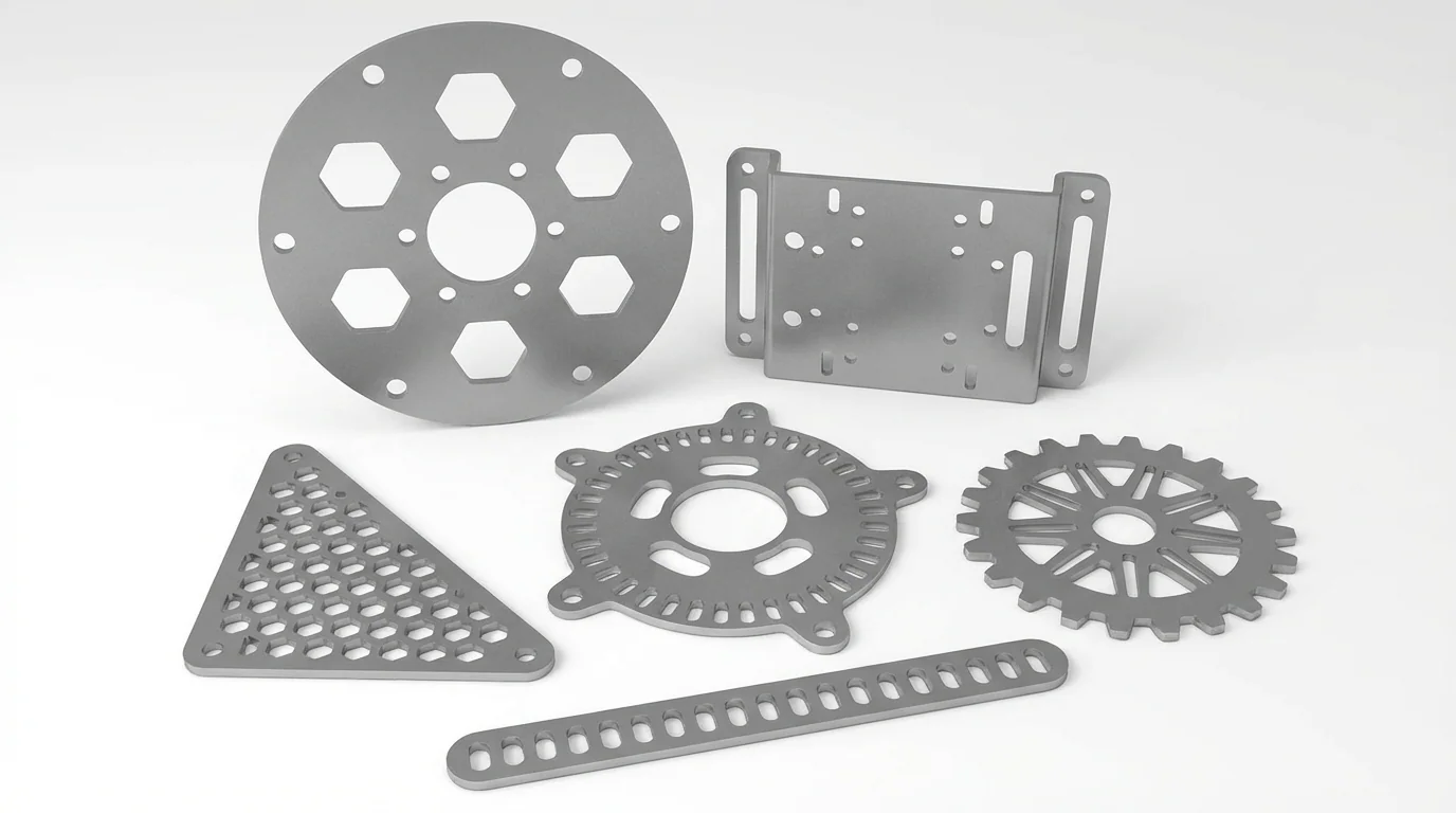
Materials / Reference
Aluminum Alloy & Temper Designations Explained
Decode 5052-H32, 6061-T6, T651, T6511, and more—then see how the complete designation changes bending, machining, welding, ordering, and drawing callouts.
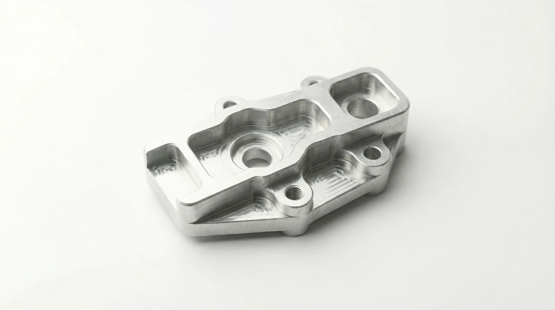
Materials / Alloy Selection
6061 vs. 7075 Aluminum: Which Alloy Should You Use?
Compare strength, stiffness, machining, welding, corrosion, anodizing, forming, cost, and drawing callouts—then choose the alloy around the part’s real requirement.
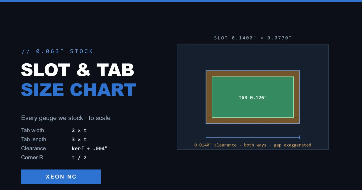
Design / Reference
Slot & Tab Size Chart
Pick a material and a gauge and get the tab width, tab length, slot size and clearance we recommend — drawn to scale, with press fit, slide fit and our self-fixturing default side by side.
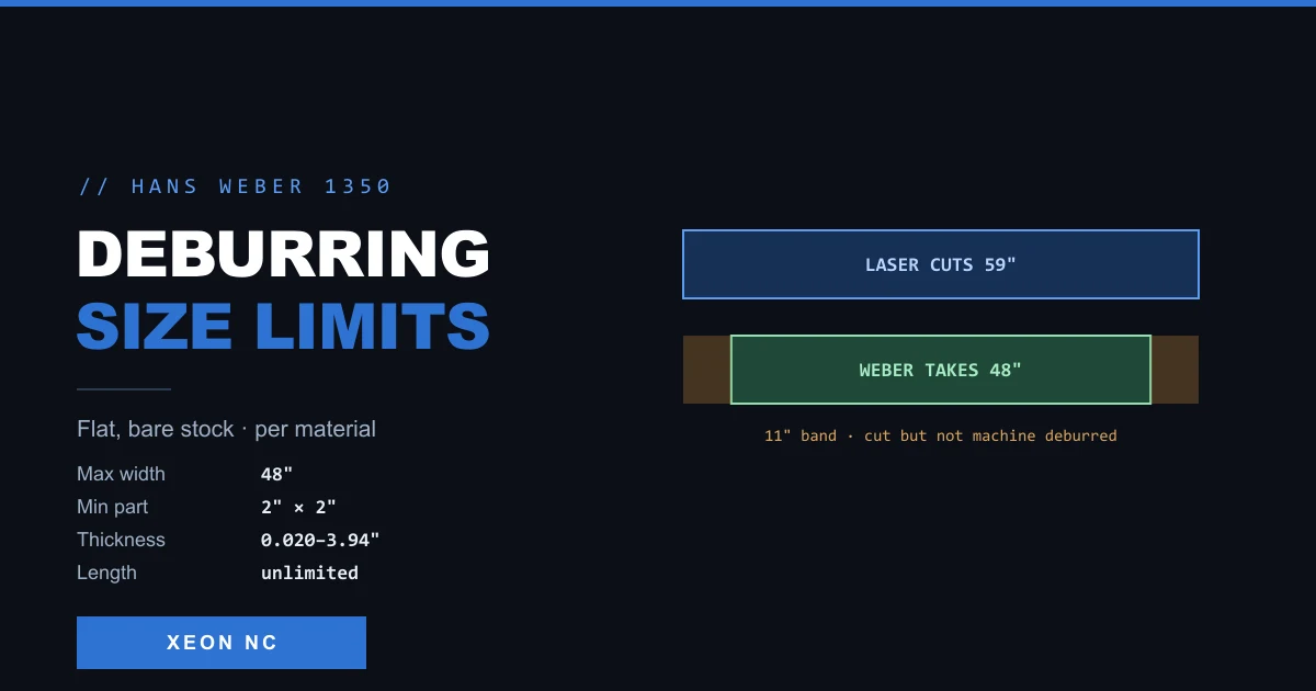
Finishing / Reference
Deburring Size Limits — Weber 1350
The processing window of our automated deburring line: 2″ minimum, 48″ maximum width, unlimited length, and the thickness range — plus which materials run, which need confirming, and which we exclude outright.
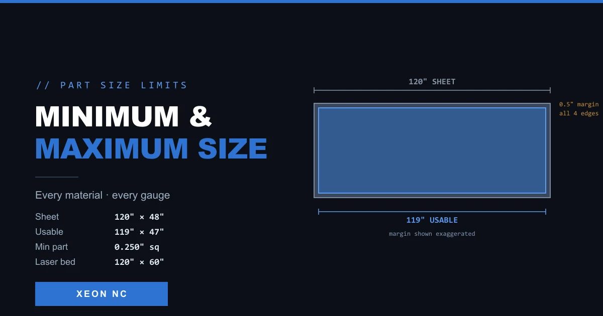
Materials / Reference
Minimum & Maximum Part Sizes
How small and how large a part can be, for all 126 SKUs we stock — with the three limits that decide it, and a checker that tests your flat blank against the whole catalog at once.
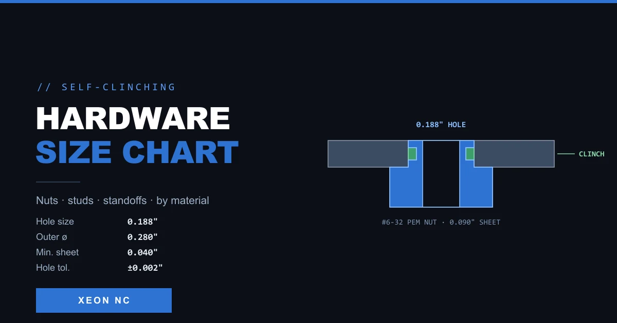
Hardware / Reference
Hardware Size Chart
Hole size, outer diameter, and part numbers for every self-clinching fastener we stock — nuts, flush nuts, studs, standoffs, blind standoffs. Pick your sheet material and gauge and the whole catalogue marks what will actually clinch.
Fasteners / Reference
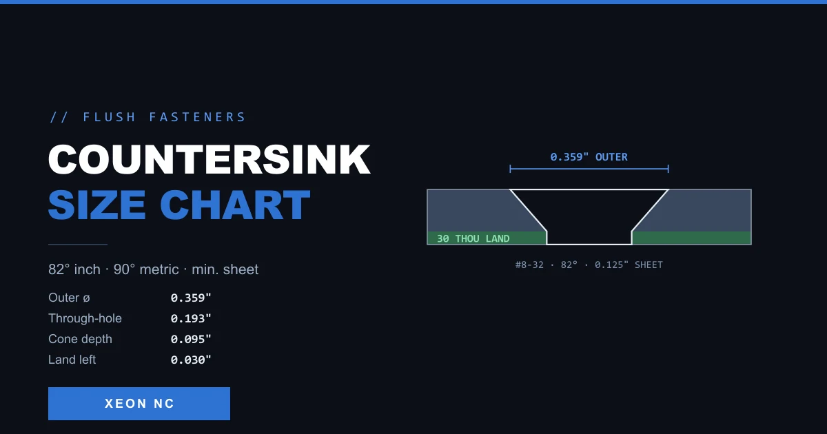
Countersink Size Chart
Outer diameter, through-hole, and cone depth for every 82° inch and 90° metric seat we tool — plus the number no fastener catalogue gives you: the minimum sheet thickness each size needs before the cone leaves a knife edge instead of a seat.
Threads / Reference
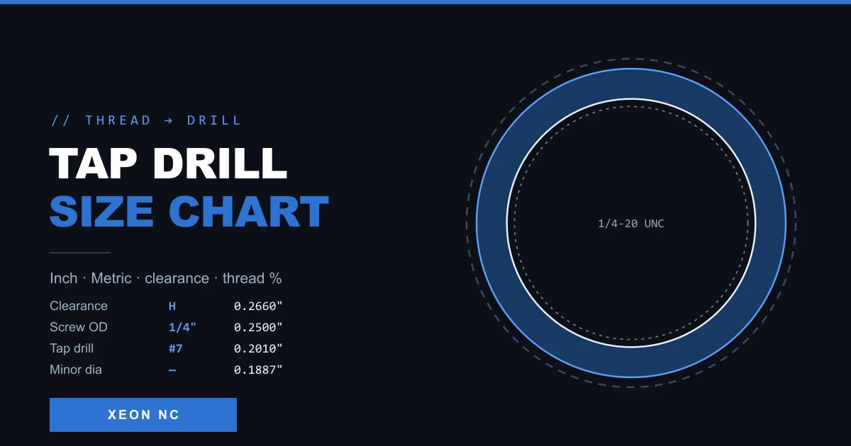
Tap Drill Size Chart
Tap drills, clearance drills, and minor diameters for every inch and metric thread — with a live thread-percentage dial instead of somebody else’s fixed 75% and 50% columns, and a sheet-thickness check that says whether the thread will actually hold.
Materials / Reference
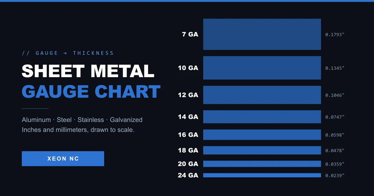
Sheet Metal Gauge Chart
Every gauge from 3 to 30 in inches and millimeters, for aluminum, mild steel, stainless, and galvanized — with cross-sections drawn to scale, a two-way converter, the thicknesses we stock, and a DFM Preflight on every gauge.
Laser Cutting
Complete Fiber Laser Cutting Design Guide
Everything you need to know to design parts for our fiber laser: file formats, tolerance stack-ups, minimum feature sizes, kerf compensation, and gang-sheet nesting strategies for production savings.
CAD File Preparation
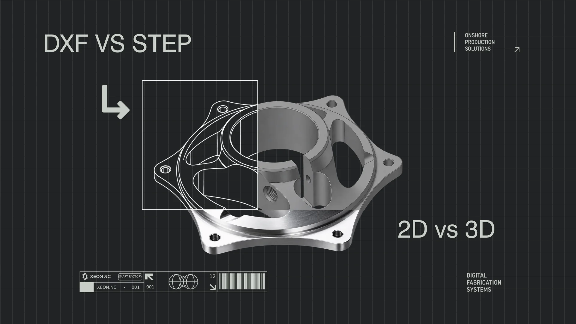
STEP vs. DXF: Which File Should You Send?
DXF communicates a 2D cutting profile. STEP can carry the finished 3D part. Learn which format gives your fabricator the information needed to quote, validate, and manufacture your design.
CAD File Preparation
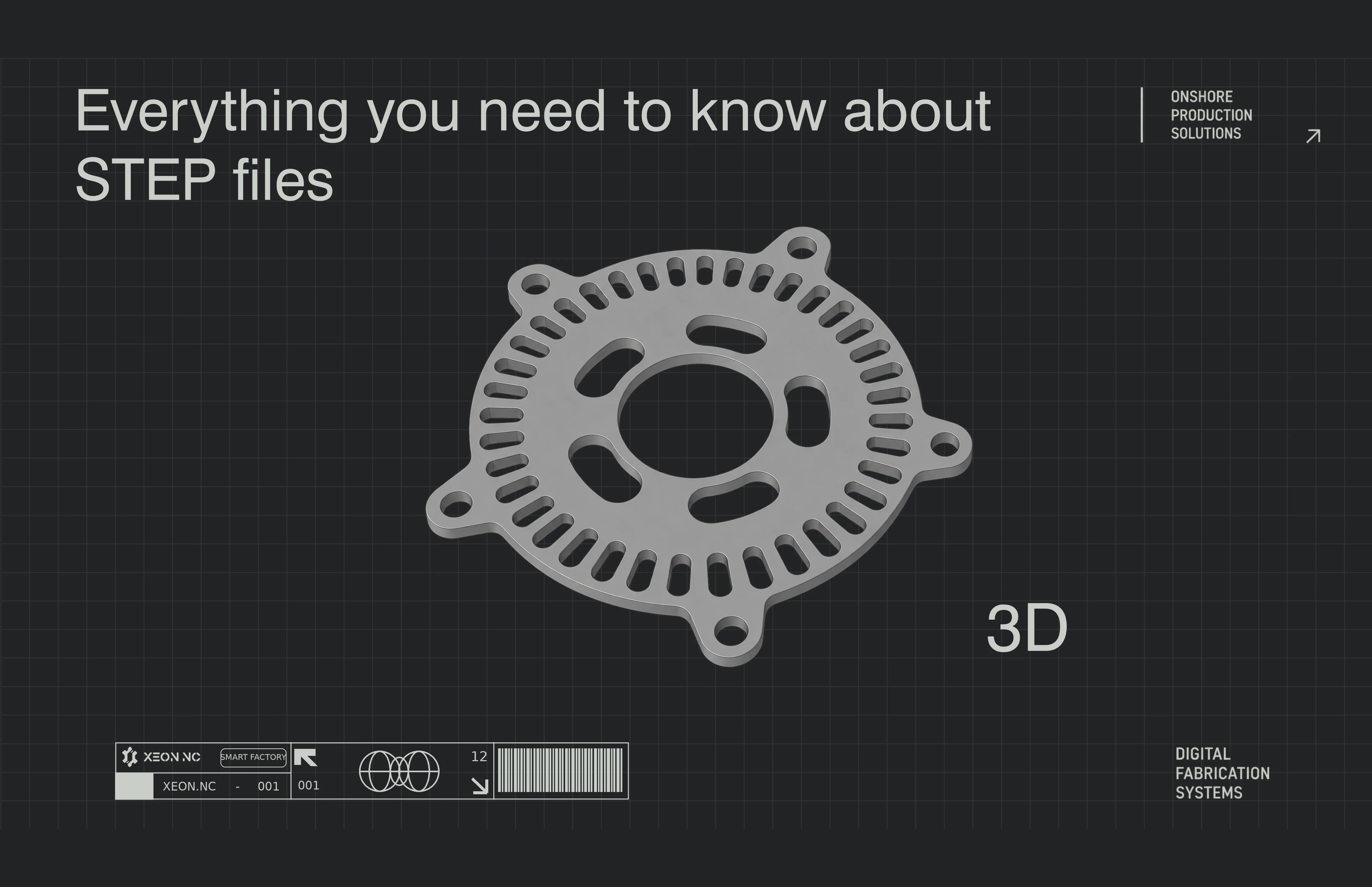
Everything You Need to Know About STEP Files
A complete guide to STEP and B-rep geometry, AP203, AP214, AP242, export settings, feature recognition, automatic quoting, manufacturing simulation, and validation.
Design Rules
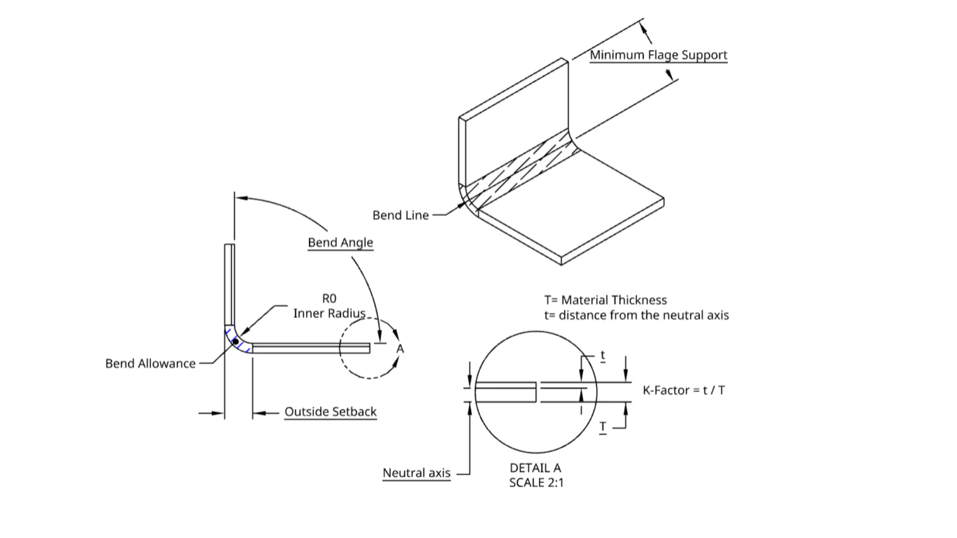
DFM Rules & Error Code Lookup
Every warning our instant quote can raise, documented and searchable. Type the code from your quote and get the rule in plain English — what it means, why the process behaves that way, and exactly how to fix it in CAD.
Bending / Onshape
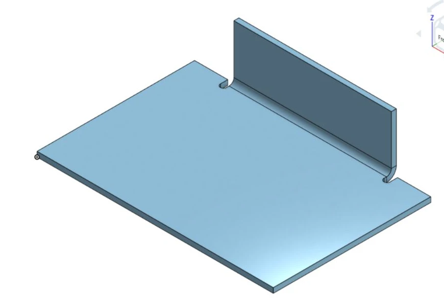
How to Design Bend Reliefs in Onshape
Three Onshape screenshot examples with formed and flat views. Compare obround and rectangular slots, understand width and depth, and inspect a full-width flange.
Bending / Box Corners
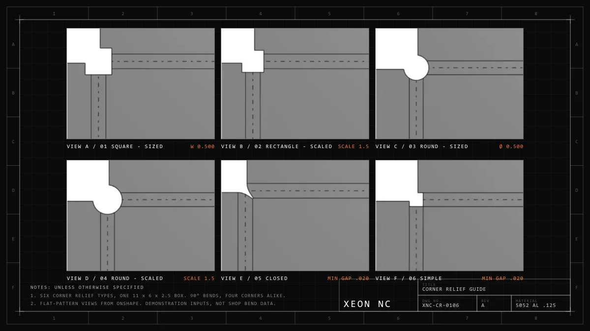
Sheet Metal Corner Relief: Six Onshape Types Compared
One 0.125″ 5052 box, six corner reliefs. Formed corner and flat pattern side by side on drawing sheets, what each type is good for, what to watch, and how the demo inputs map to Xeon NC shop numbers.
Bending / Box Corners
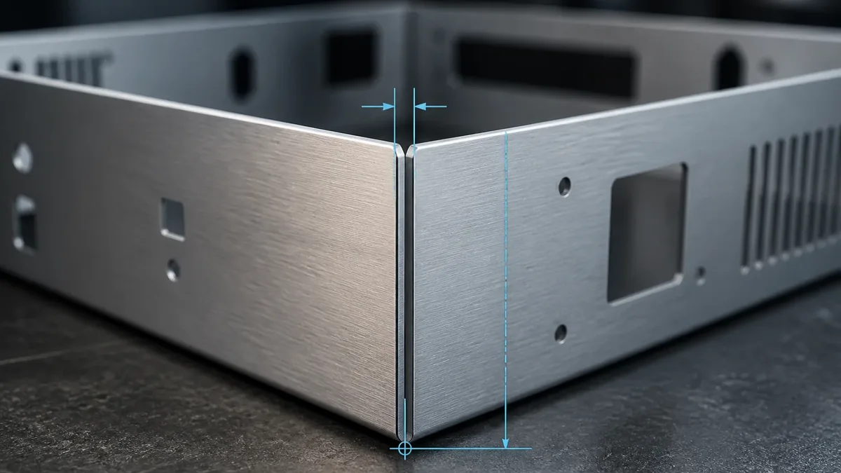
How to Keep Perpendicular Corner Flanges from Colliding
Check relief-opening size, seam clearance and the forming sequence separately. Start with material-specific corner guidance and current bend data.
Bending / Controlled Deformation
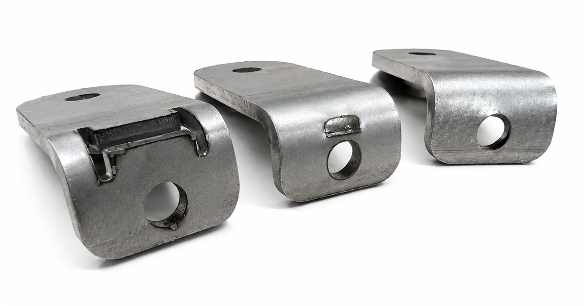
Hole Pull-Through: Designing Controlled Deformation
When a critical hole cannot move away from a bend, a bow-tie relief can isolate it and a straight slit can redirect the strain. Both strategies can protect the feature. Both reduce local strength.
Bending / Feature Placement
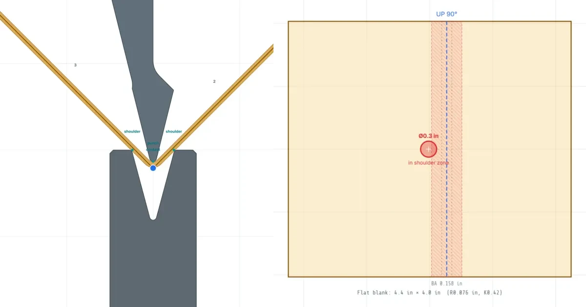
How Close Can a Hole Be to a Bend?
Two things ruin a hole near a bend: the metal stretching, and the die shoulder sitting under it. The second is usually the bigger number — and you can see it on your own part in the bend simulator.
Bending / Inside Radius
Sheet Metal Bend Radius: How to Choose the Correct Inside Radius
In air bending the die makes the radius, not the punch. The five radii we actually form, why the 1T rule breaks inside a die band, minimum bend radius by alloy and temper, and everything that moves downstream when the radius changes.
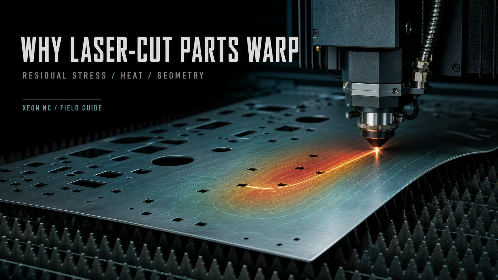
Laser Cutting / DFM
Why Laser-Cut Parts Warp
How residual stress, heat, geometry, and cut strategy interact—with a practical risk matrix and interactive warping preflight.
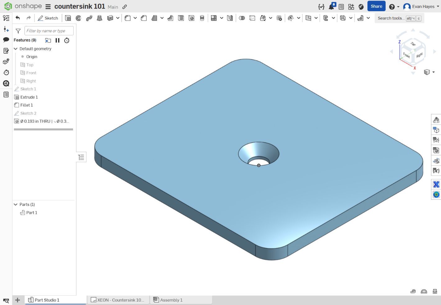
CNC / Onshape Workshop
Countersinks in Onshape: Model, Check & Draw
Set the bore, cone, and entry side using Xeon’s tool table. Check the remaining material and create a technical drawing.
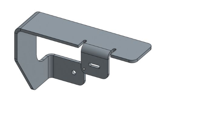
Bending / Drawing Practice
How to Make a Sheet Metal Technical Drawing
A real Onshape bracket: inside radii, formed inspection dimensions, and flat development using Xeon’s 5052 tooling data.
Bending / Drawing Practice
How to Dimension a Sheet Metal Drawing
Where you put the datum decides which errors add up. Baseline vs chained dimensions, what to tolerance, and why an angle band becomes a length error at the flange tip.
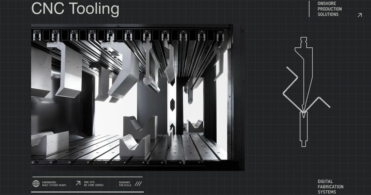
Bending / Design Guidelines
Complete Sheet Metal Bending Guidelines
A production-minded guide to formed STEP files, bend data, minimum flanges, radii, hole spacing, reliefs, channels, tolerance stack-up, and preflight.
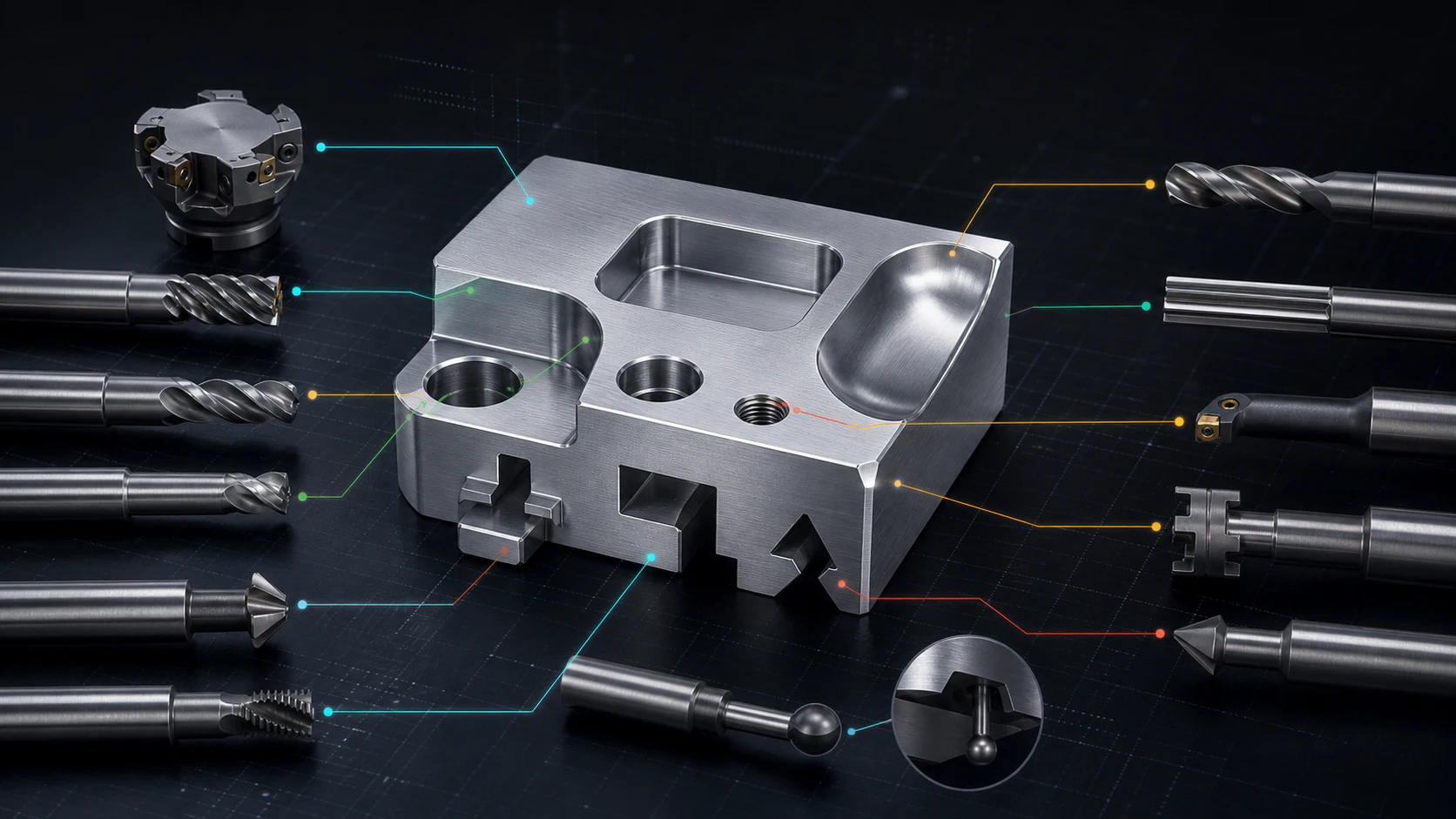
CNC Machining / Cutting Tools
CNC Milling Tools: Matching the Cutter to the Feature
How end mills, face mills, drills, ball-nose tools, thread mills, T-slot cutters, dovetail cutters, and lollipop tools create specific CNC features.
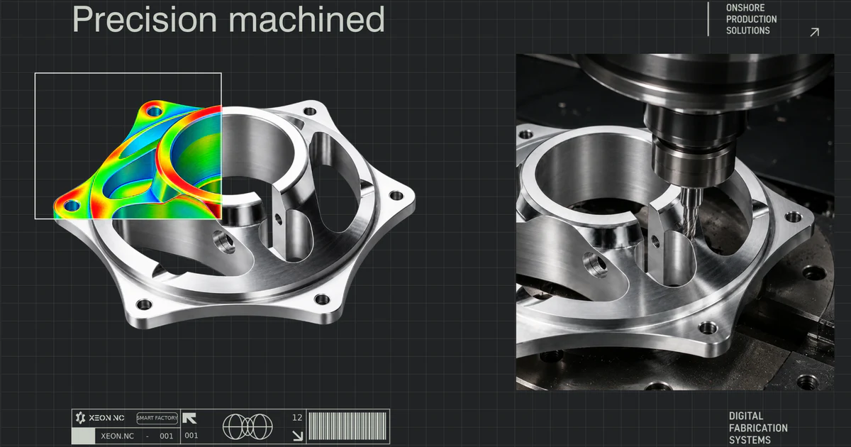
CNC Machining / Tolerancing
Precision Machined. To the Thousandth.
How nominal dimensions become acceptance limits — including how ISO 2768 medium tolerances widen as the controlled dimension grows.
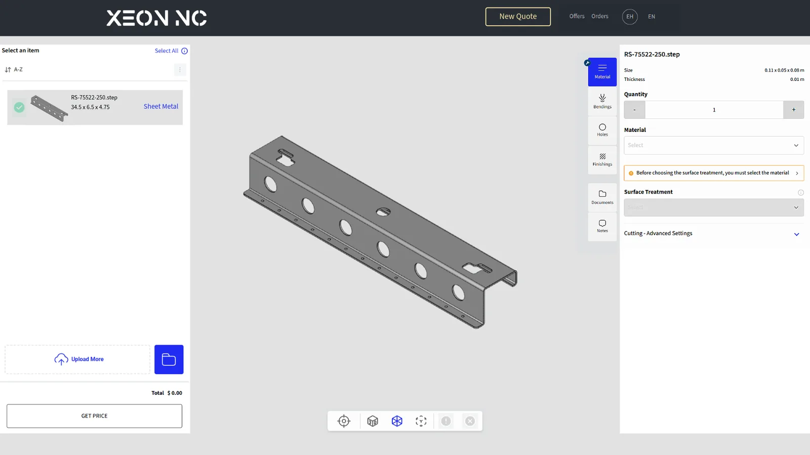
Getting Started
Instant Quoting Design Guide
A step-by-step walkthrough of the Xeon NC quoting platform — material selection, bend setup, hole processing, finishing options, document upload, and notes for the manufacturer.
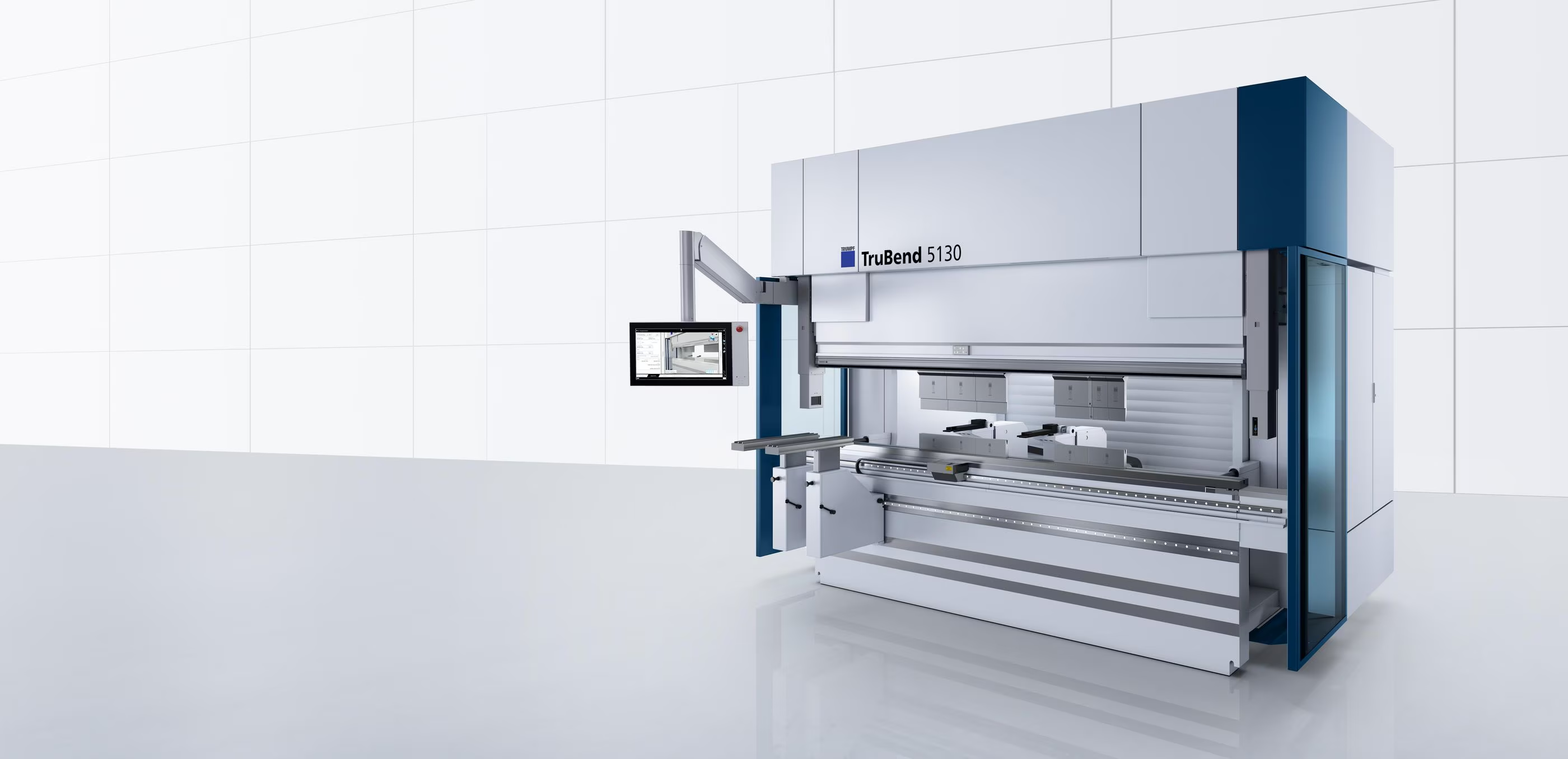
Bending
CNC Press Brake Bending Guide
Bend allowance calculations, K-factor by material, minimum flange lengths, inside radius selection, and how to design multi-bend parts with accurate flat-blank dimensions.
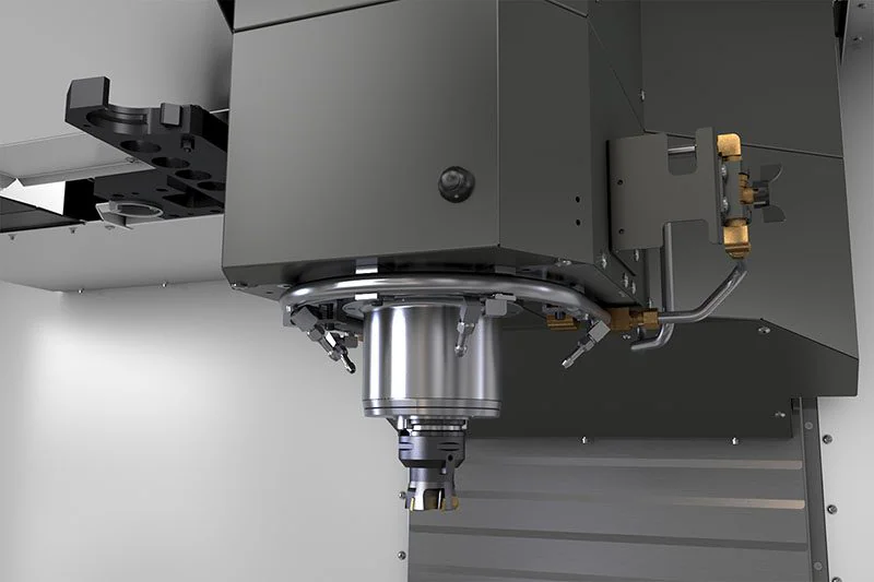
CNC Machining
CNC Machining Design Guide
Internal corner radii, pocket depth ratios, thread call-outs, GD&T callout conventions, and surface finish selection for aluminum, steel, and engineering plastics.
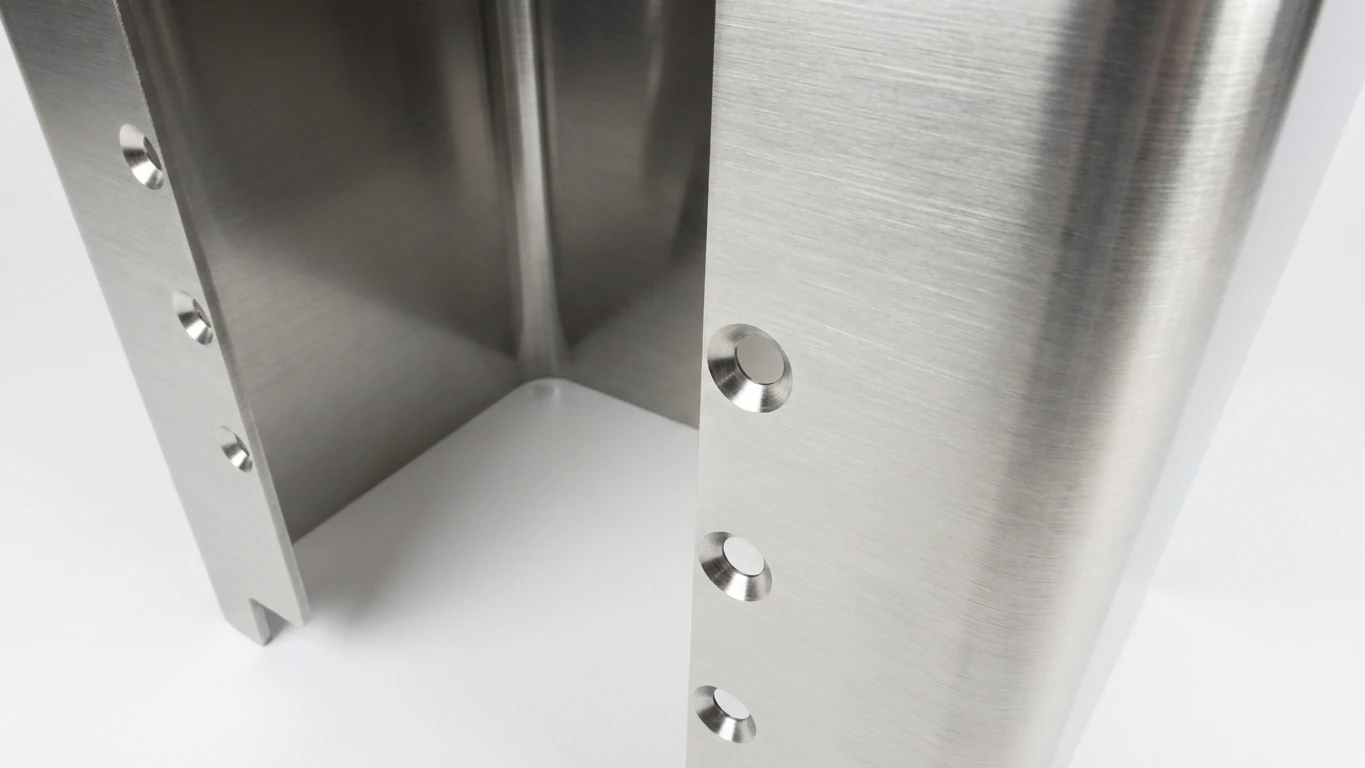
CNC Machining / Calculator
Countersink Geometry Calculator
Live cross-section of a countersunk hole: 82° or 90°, outer diameter, through-hole, thickness, remaining land, and top or bottom side — from Xeon NC tooling tables.
CNC Machining
Countersinking for Sheet Metal
When to countersink, mechanical benefits, thin material limits, choosing the correct angle (82°, 90°, etc.), and how to specify countersinks perfectly in CAD.
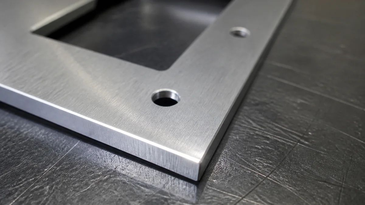
Surface Finishing / Safety
Breaking Sharp Corners on Sheet Metal Parts
Laser-cut blanks leave knife edges and needle corners. Recommended edge break and outside-corner radius by material and thickness — mostly so nobody gets cut unpacking the part.
Surface Finishing
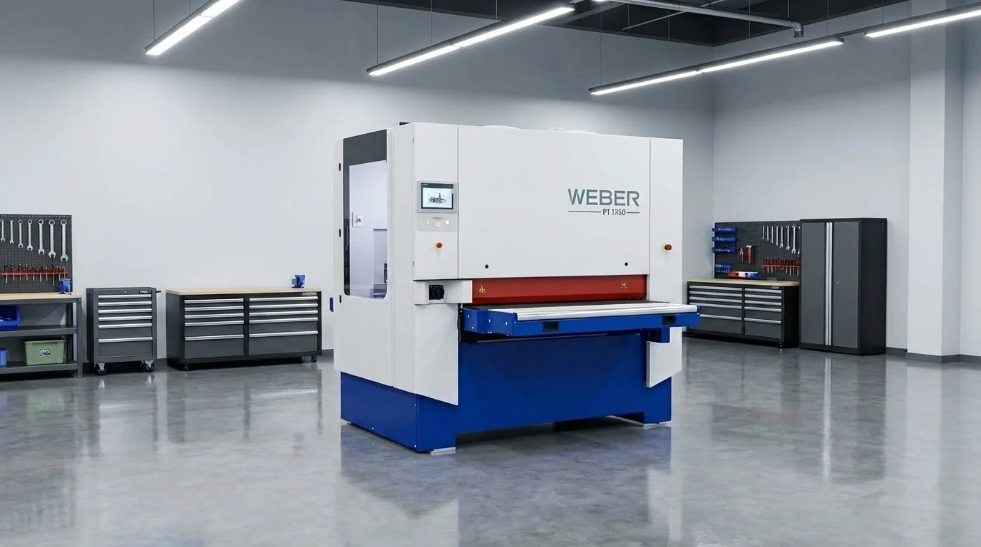
Deburring & Surface Finishing
Weber 1350 deburring operations: edge rounding, Scotch-Brite finishing, oxide removal, part size limits, and design rules for through-feed processing.
Getting Started
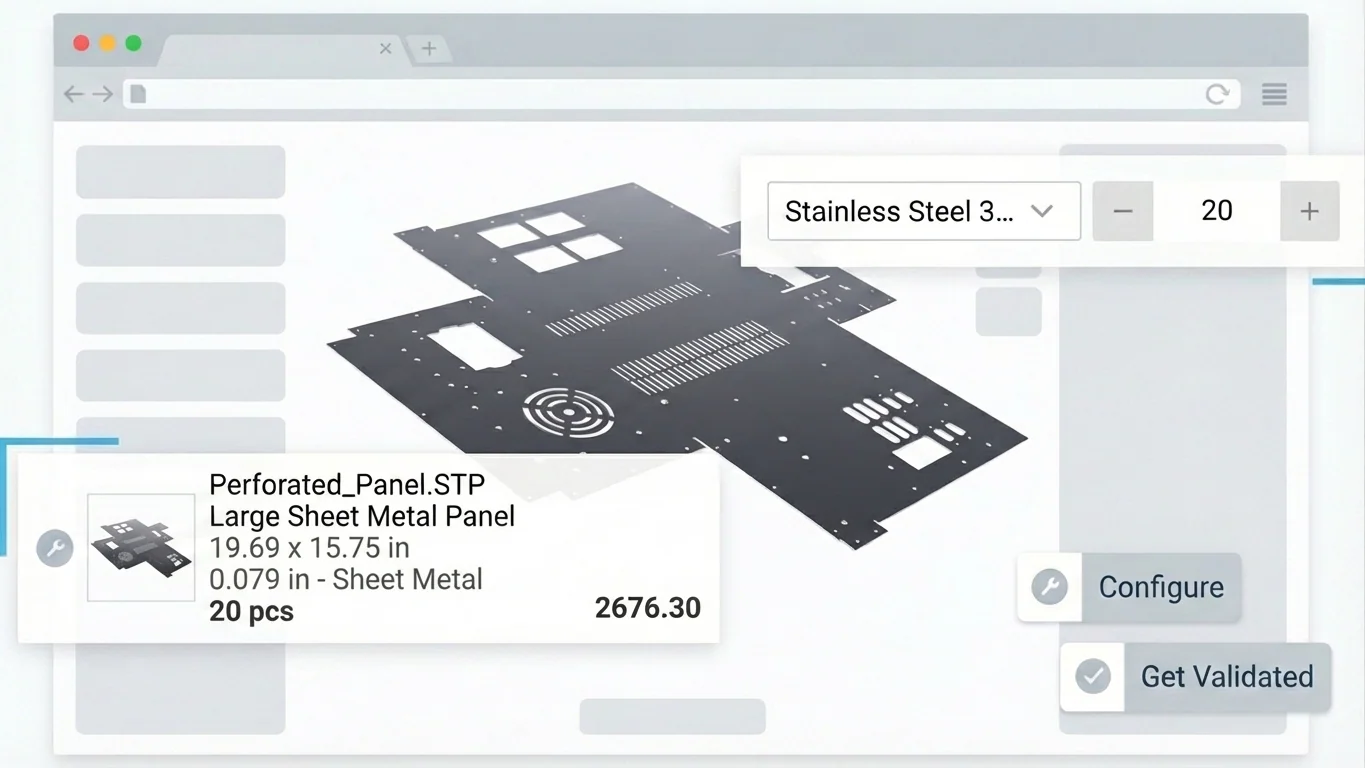
How to Prepare Your CAD File
Accepted file formats (DXF, STEP, STL), step-by-step export guides for SolidWorks, Inventor, and Onshape, plus a pre-flight checklist for every service.
Getting Started
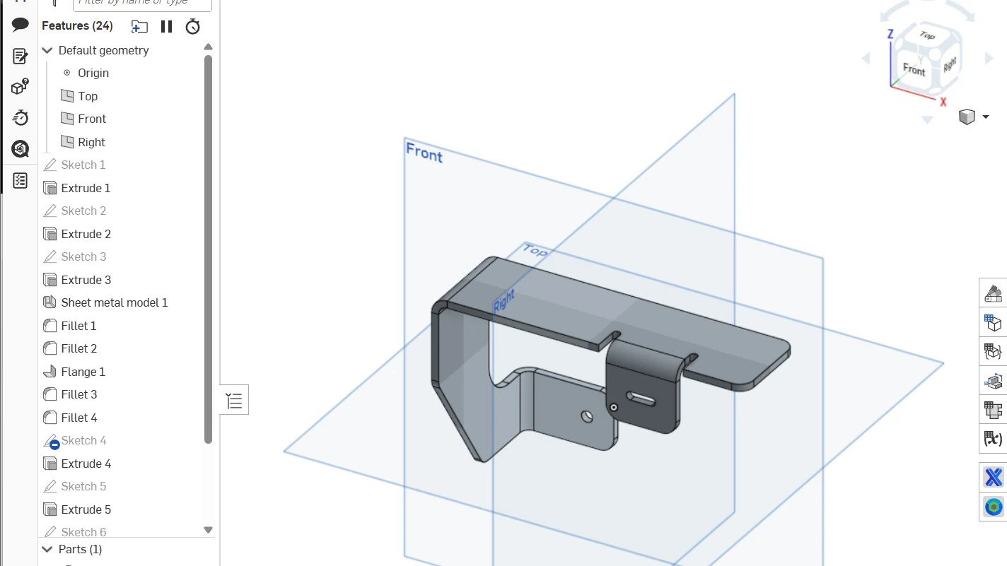
Exporting a Sheet Metal STEP File from Onshape
Every click and every setting, with screenshots — which AP version to pick, the units checkbox that silently scales your part by 10×, and why to send the folded model instead of a flat pattern.

Weldment Design
Welding Symbols & Joint Types
A visual AWS-based guide to the arrow, reference line, basic weld symbols, supplementary marks, dimensions, contours, and the five foundational joint arrangements.

Weldment Design
Welding Defects & Laser-Cut Design Tips
Diagnose 12 common weld conditions and design better laser-cut joints with intentional fit-up, assist-gas edge preparation, material selection, distortion control, and inspection access.
Laser Cutting
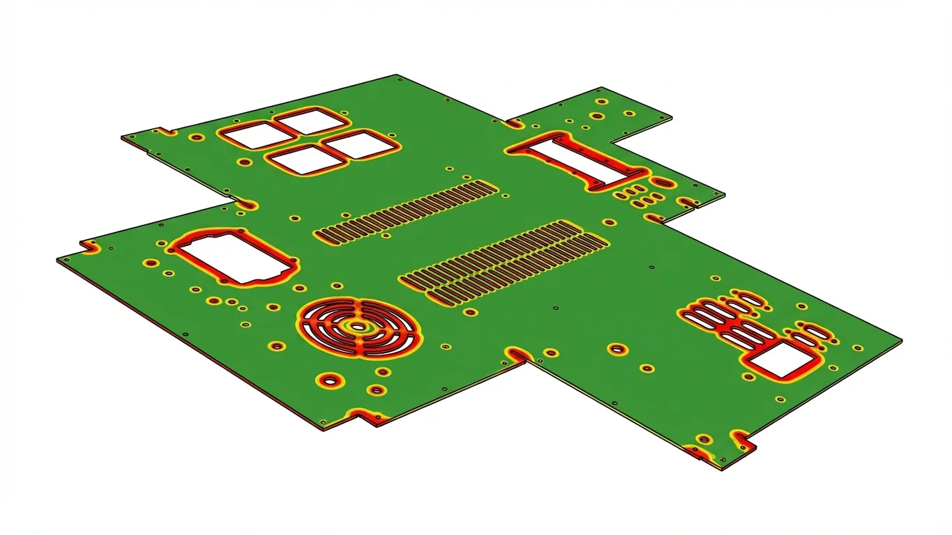
The Heat-Affected Zone (HAZ)
Understanding how thermal exposure alters material composition during laser cutting. Learn how thickness, hot spots, and density impact part hardness and warp.
Laser Cutting
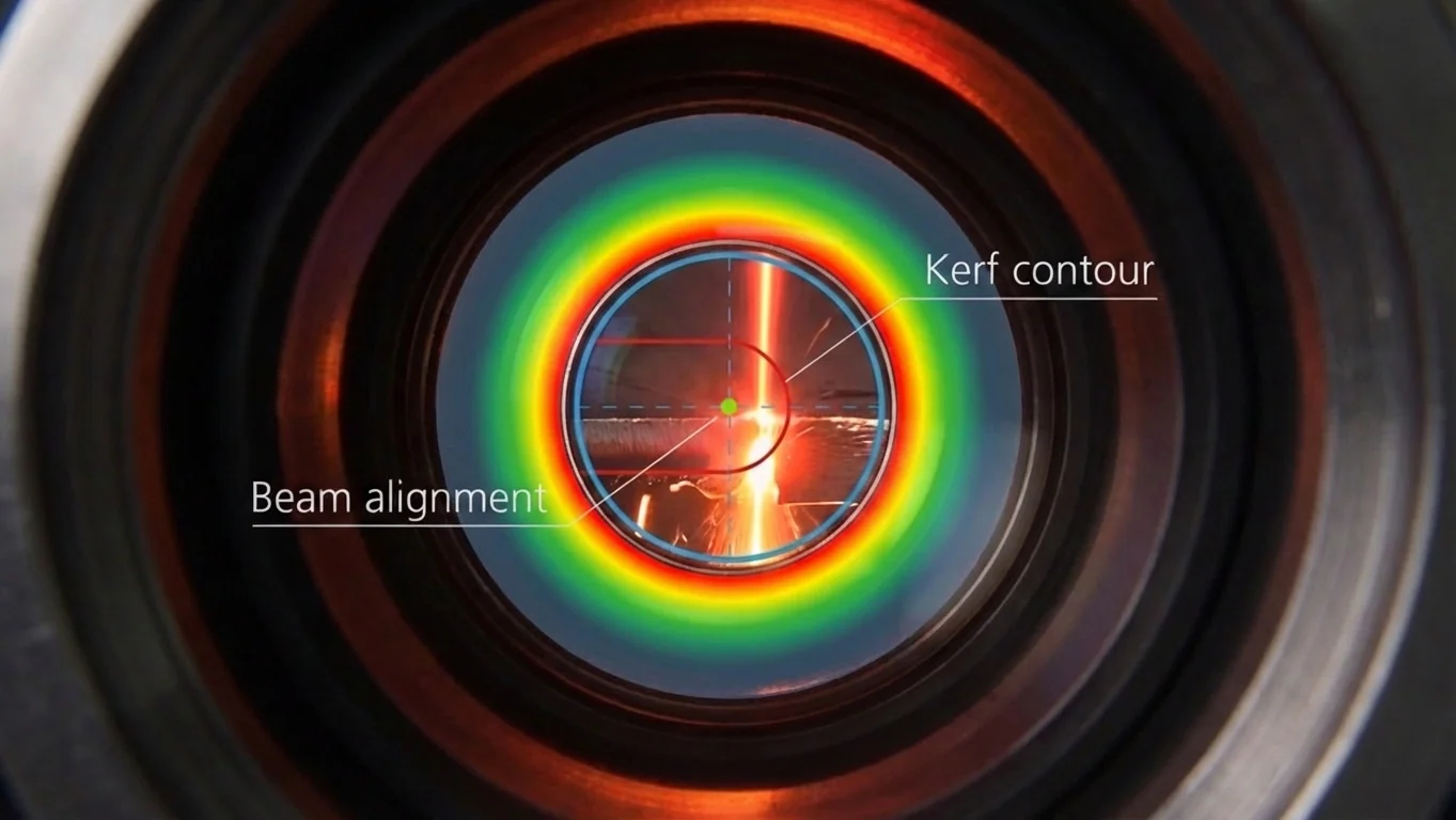
Understanding Laser Kerf
Learn what laser kerf is, why software toolpath offset is critical, and how material thickness directly impacts your minimum allowable cut width and hole sizes.
Finishing
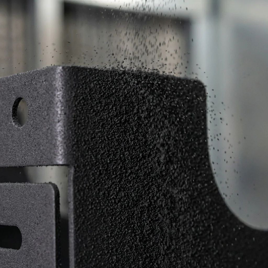
The Powder Coating Process
Explore dry finishing, critical part hanging requirements, and why powder coating severely outperforms wet paint and anodizing in volume manufacturing durability.
3D Printing
3D Printing Design Guide
Wall thickness minimums, overhang rules, thread insert heat-set best practices, supported vs. unsupported geometry, and material selection guide for FDM and SLA parts.
Laser Cutting
How to Prepare Your CAD File
A step-by-step walkthrough for preparing DXF and STEP files from AutoCAD, Fusion 360, and SolidWorks — ready to submit with zero back-and-forth.
Finishing
Anodizing Guide: Type II vs. Type III
When to specify Type II vs. Type III hardcoat anodize, how anodizing affects dimensional tolerance, color options, masking considerations, and how to call it out on your drawing.
Materials
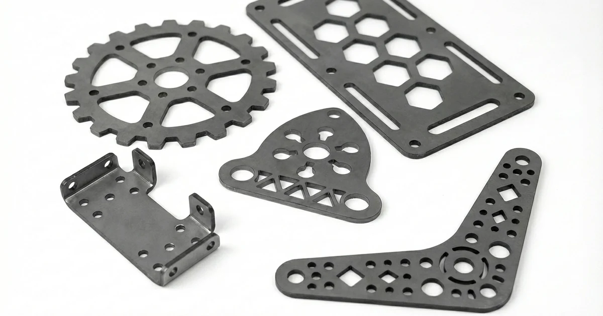
Mild Steel for Laser Cutting
Compare A1008 cold rolled, A1011 hot rolled and HRPO, A36 plate, and coated sheet—then choose the right cut edge, fabrication route, finish, and ordering callout.
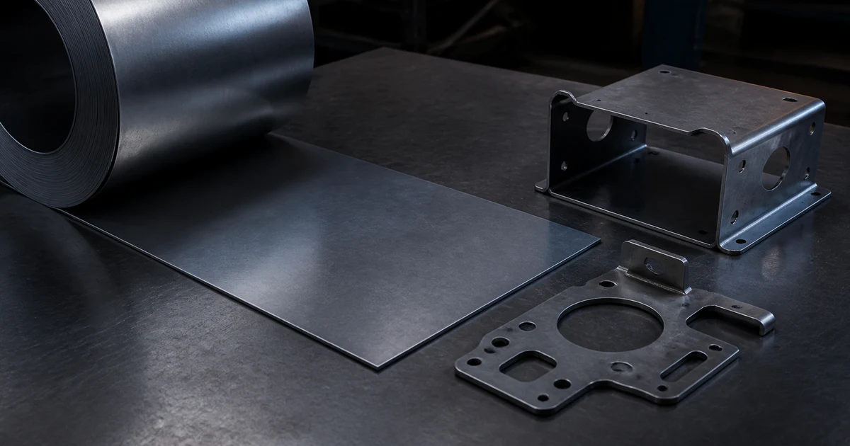
Materials
Understanding Cold-Rolled Steel Sheet Metal
What cold rolling changes, how ASTM A1008 designations work, and how to specify thickness, laser cut, bend, weld, coat, and protect carbon steel sheet for U.S. production.
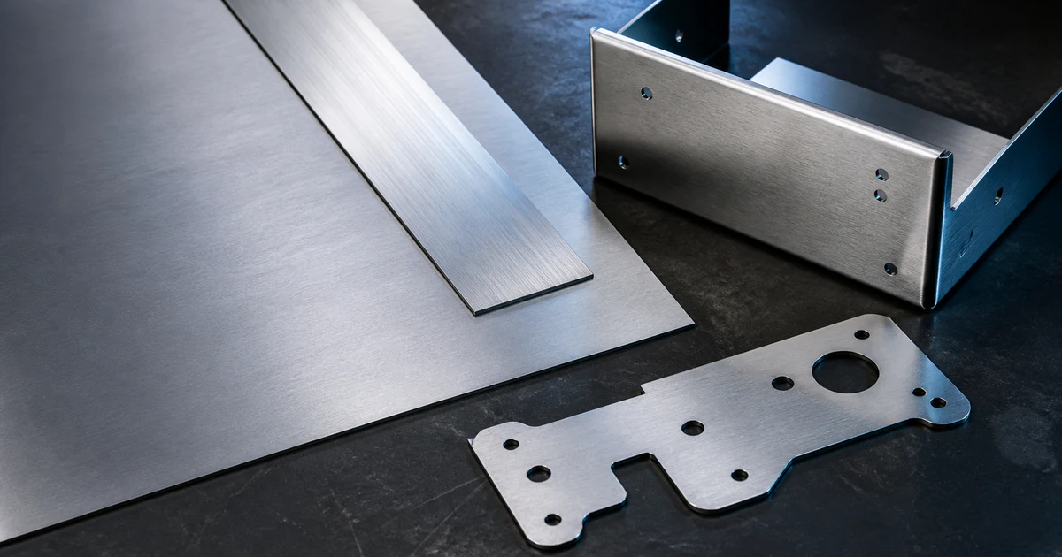
Materials
Stainless Steel Sheet Metal: 304, 316 & More
A U.S.-focused guide to 201, 301, 304/304L, 316/316L, 321, 409, 430, and 17-4 PH — specifications, finishes, laser cutting, bending, welding, passivation, and drawing callouts.
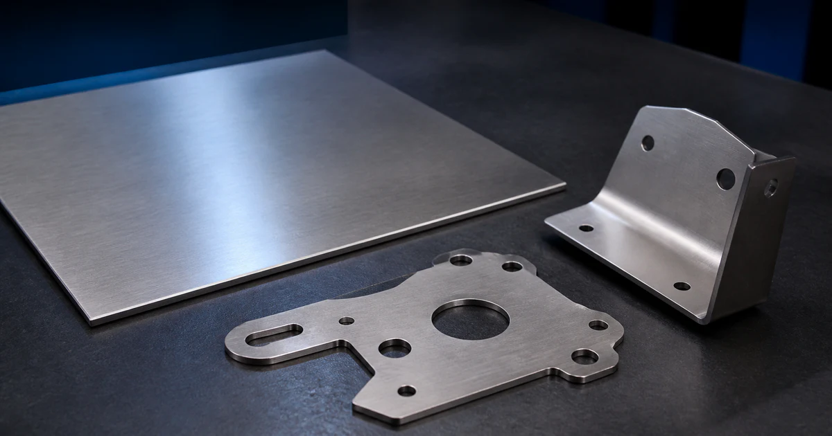
Materials
Titanium Sheet Metal: Grade 2, Grade 5 & More
A U.S.-focused guide to Grades 1, 2, 3, 4, 5, 7, 9, 12, and 23 — ASTM and AMS specifications, laser cutting, bending, welding, finishes, safety, certification, and drawing callouts.
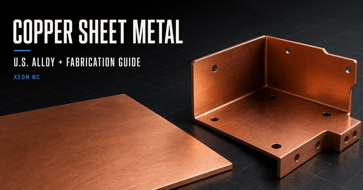
Materials
Copper Sheet Metal: U.S. Alloy & Fabrication Guide
How to select and specify C11000, C10100, C10200, and C12200 copper sheet in the U.S. — ASTM product standards, tempers, exact thicknesses, laser cutting, bending, joining, finishes, and drawing callouts.
Materials
Sheet Metal Material Selection Guide
Choosing between 5052-H32, 6061-T6, A36 HR steel, 304 stainless, and brass for your project — a practical comparison of machinability, corrosion resistance, strength, and cost.
Laser Cutting
Understanding Tolerances & Inspection
A practical guide to laser cutting tolerance stacks, how we inspect parts, what ±0.005″ really means in production, and when to call out tighter tolerances on your drawing.
CNC Machining
The Engineer's Guide to GD&T
Decoding Geometric Dimensioning and Tolerancing: A complete breakdown of symbols, feature control frames, and how they apply in precision manufacturing.
Bending
Picking Tooling for the Bend
How to choose the right punch and V-die from material, thickness, and target radius — air bending fundamentals, the V × T rule, the 16% radius rule, tonnage math, and Trumpf / WILA tooling reference.
Bending
Our Press Brake Tooling Library
Every punch and V-die we run, the material thickness each die covers under the 6–12 die-width rule, and full technical data for each WILA OW / EV tool — with a thickness coverage map and per-tool spec cards.
Bending
The Bend Affected Zone (BAZ)
How deformation around the bend radius impacts hole placement, slot positioning, and feature design in sheet metal — with minimum clearance formulas and material-specific rules.
Bending
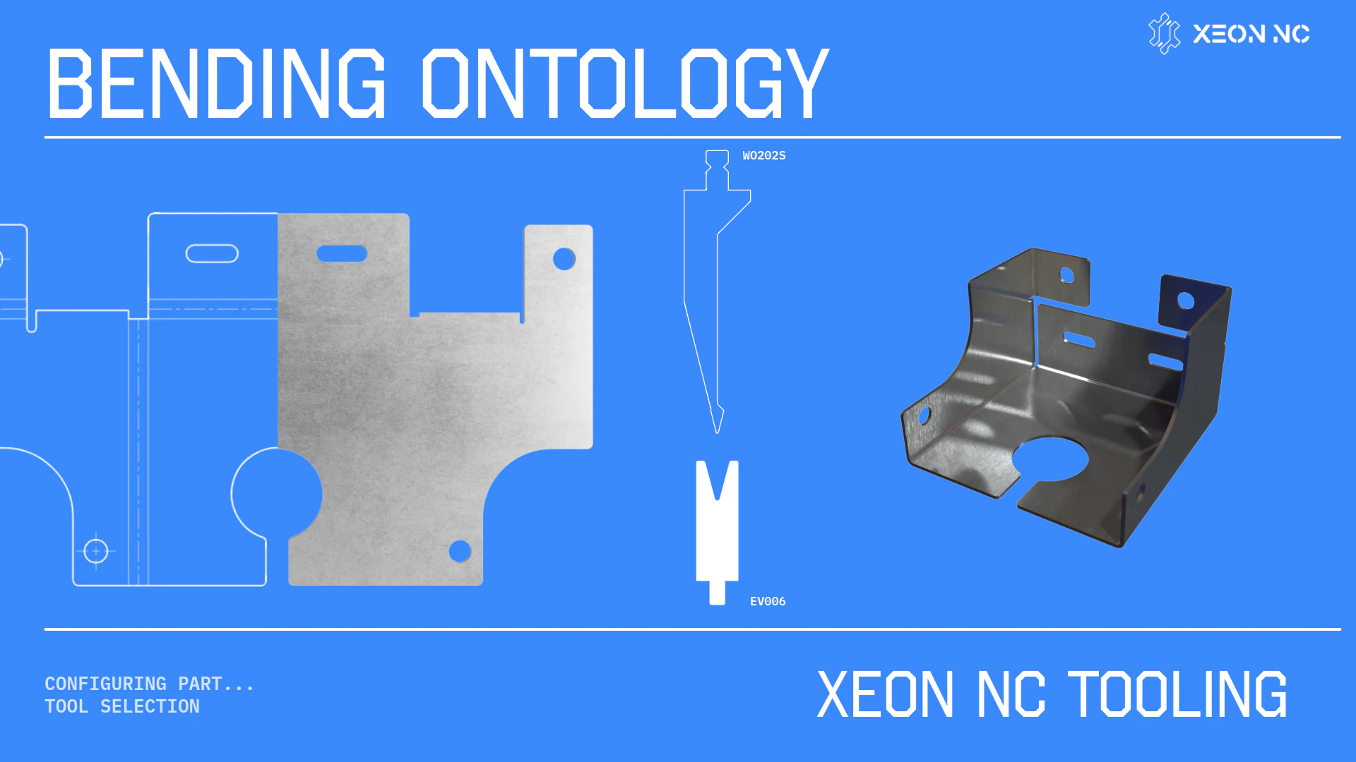
Bending Ontology & Material Specs
The complete bending vocabulary — bend deduction, bend allowance, K-factor, inside radius, neutral axis, and minimum formed flange — plus a live lookup tool for tooling, K-factor, and bend deduction on every material we run.
Bending
Reverse Bend Clearance Checker
Interactive tool: enter your base dimension and return flange height to see whether our punches can reach the bend. Envelopes computed live from the real traced tool profiles.
Bending
Part-on-Part Collision
The interference that only exists mid-stroke. Why springback forces the brake to over-bend past your angle, how far that actually moves a flange, and how much clearance a formed feature needs to survive it — plus two interactive 3D parts you can run through the same press brake stroke, one that collides and one that clears.
Try a different direction.
No guidelines match these filters. Try a broader term or choose another topic.
02 / Put it into practice
A better design.
A part ready to build.
Put the details to work. Bring your drawings to Xeon NC and take the next step toward production.
Get an instant quote