Why Good Parts Don’t Fit: Sheet Metal Tolerance Stacks
Start with the gap that must survive.
The important dimension is often the space between two parts. Neither part drawing contains that space on its own.
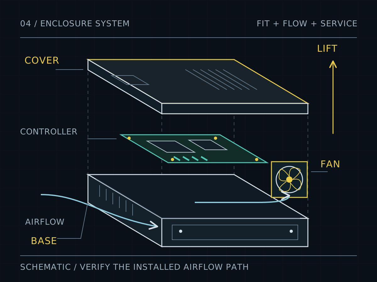
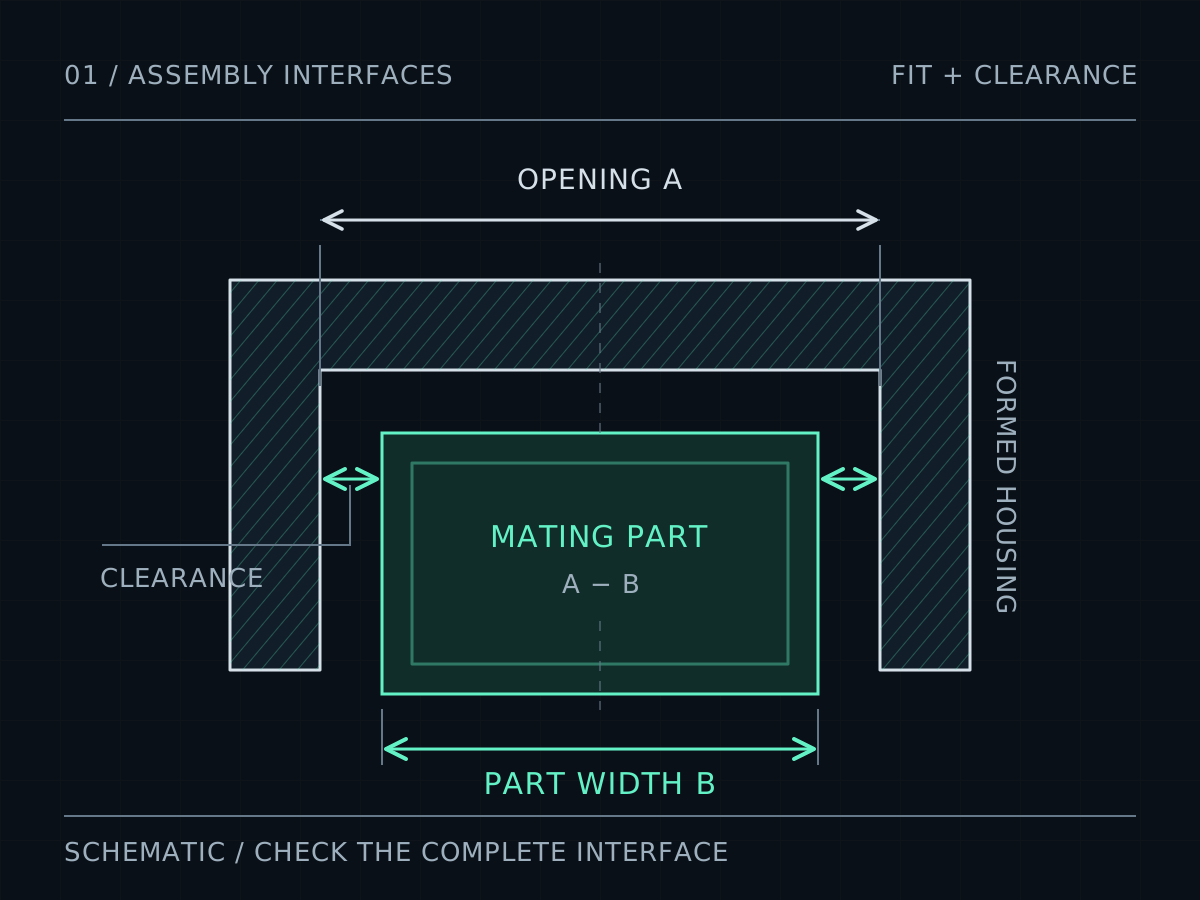
Consider a removable cartridge that slides between two formed enclosure walls. The housing can be narrow but acceptable. The cartridge can be wide but acceptable. Both can receive acceptable coating. Their combined clearance may still be too small for reliable insertion. Tightening every dimension obscures the issue: the design needs a controlled relationship between the final mating surfaces.
Write that relationship before assigning tolerances. Identify what must happen: the cartridge must slide in without force, the cover must seat without pulling the walls inward, or a connector must enter without the fasteners steering it into place. Then define an acceptance condition for that function. A clearance requirement should say whether it applies before or after finishing, at room temperature or across an operating range, and in a free or assembled state.
A one-dimensional stack is appropriate when a single direction controls the fit. It cannot represent every alignment problem. Angular error, nonparallel walls, hole-pattern position, and interference along an insertion path can require a two- or three-dimensional analysis.
Trace one continuous dimension loop.
For a cartridge between two coated walls, use the inside housing width and the outside cartridge width at the same section. Starting from unrelated outside dimensions introduces thicknesses, bend geometry, and additional uncertainty that may be unnecessary.
Those four faces are the two inside enclosure walls and the two outside cartridge faces. Each layer reduces total width clearance once. If the housing opening or insert width is already specified and inspected after coating, do not subtract that coating again.
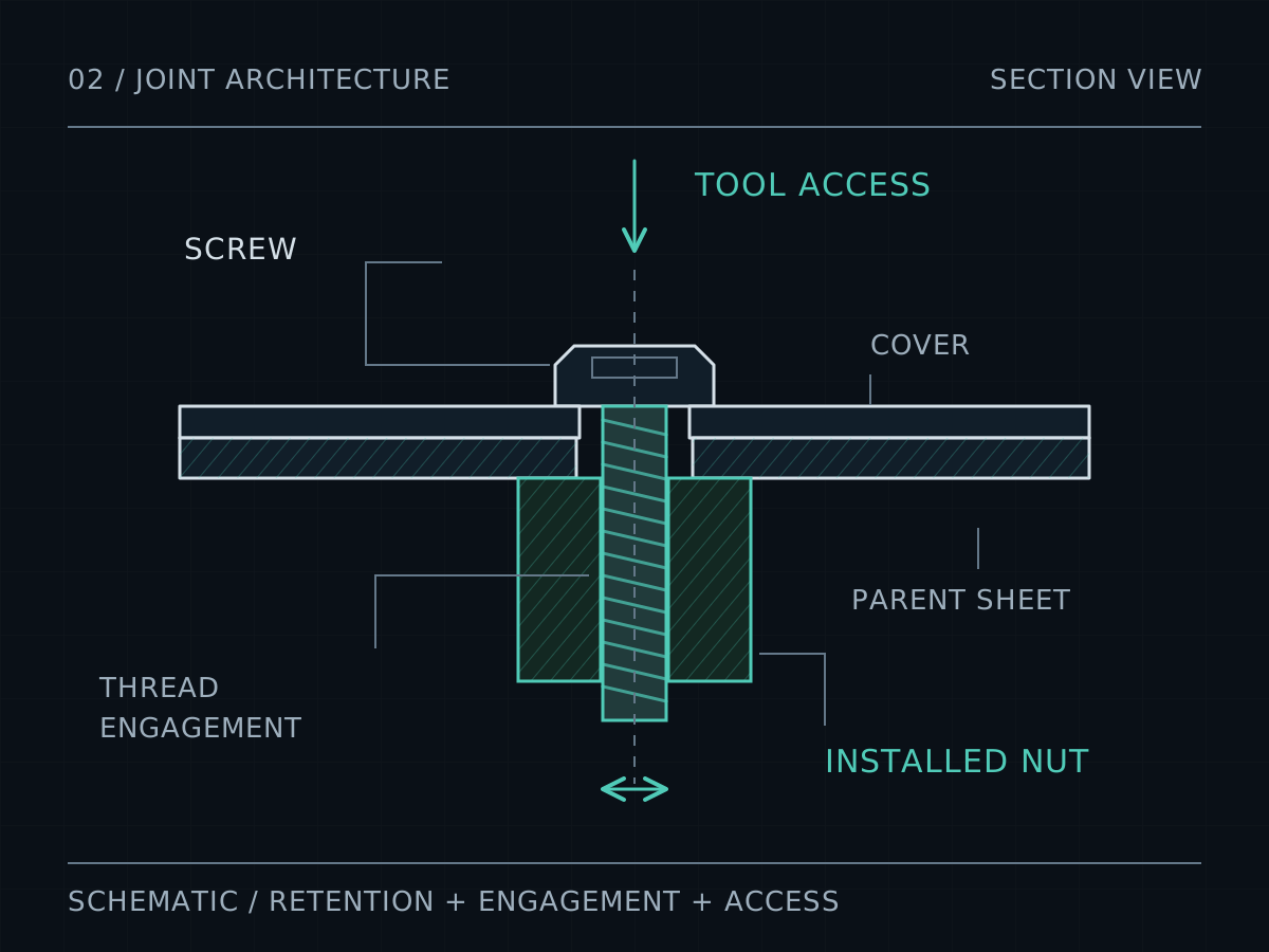
Establish the locating scheme as well. One primary seat, a locating feature, and clearance in the remaining fastening direction can prevent competing constraints. A slotted hole may accommodate variation along its length; it does not automatically solve cross-slot error, angular mismatch, or inadequate clamping area. Decide which interface locates and which fastener only clamps.
Use the formed-part dimensioning guide to communicate those relationships. A dimension chain that is easy to draw is not necessarily the shortest chain between the functional surfaces.
A 1 mm nominal gap can leave 0.10 mm.
The following values are an illustrative design exercise, not Xeon process limits or a recommended coating specification. Assume straight, parallel faces; independent part width limits; and a bounded coating thickness on each mating surface.
| Input | Nominal | Allowed half-range |
|---|---|---|
| Bare enclosure opening | 100.00 | ±0.30 |
| Bare cartridge width | 99.00 | ±0.20 |
| Coating per mating face, four faces | 0.08 | ±0.02 |
Nominal finished clearance is 100.00 − 99.00 − 4 × 0.08 = 0.68 mm. Minimum clearance uses the smallest opening, largest cartridge, and thickest coating: 99.70 − 99.20 − 4 × 0.10 = 0.10 mm. Maximum clearance is 100.30 − 98.80 − 4 × 0.06 = 1.26 mm.
If the design requires at least 0.20 mm total clearance, the example misses that requirement by 0.10 mm even though its minimum gap remains positive. These are total width clearances. They split evenly into two side gaps only if a separate locating scheme keeps the cartridge centered.
Try changing the insert to 99.20 mm in the calculator. The minimum becomes −0.10 mm: the permitted extremes now include interference. Increasing the opening, reducing insert width, masking selected faces, or revising particular tolerances can address different causes. Each choice changes a real interface and needs to be reflected in the drawing.
Explore the clearance budget.
Change the bare dimensions and coating allowance below. The tool evaluates the worst-case limits for this specific four-face, parallel-wall model. Enter actual agreed limits for your own study; the defaults are the hypothetical example above.
The calculation does not include wall bow, taper, burrs, local coating buildup, temperature, positional error, or insertion angle. Add the relevant effects to the design model or inspect the complete interface. A positive result only establishes positive clearance under the assumptions entered.
Keep angular error and finish in the same model.
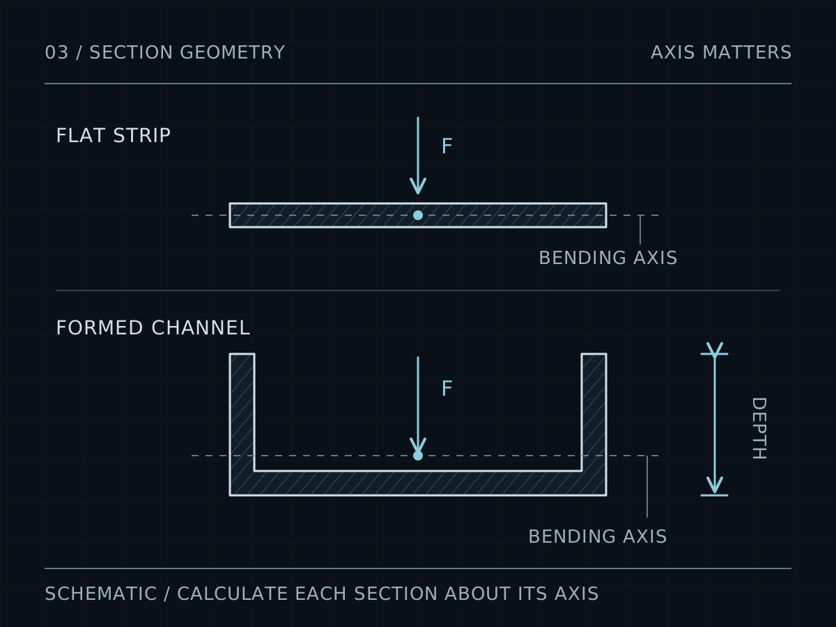
A flange is a lever. For a point a distance L from a bend, an angular deviation Δθ produces a lateral displacement of approximately L sin(Δθ) when measured relative to the nominal flange direction. At L = 80 mm and Δθ = 1°, that contribution is about 1.40 mm. The sign and sensitivity depend on the actual geometry and measurement direction; adding it blindly to every linear stack can double-count an effect already controlled by an end-position dimension.
Ask whether the functional requirement concerns the bend angle, the free-state tip location, or a seated assembly. Those are different measurements. A drawing that controls a final interface position can be more directly useful than unrelated tight limits on each upstream feature.
Finishing also belongs in the interface definition. Coating on a hole reduces its available diameter; coating on a pin increases its diameter. Masking, final machining, or a clearance change must be specified deliberately. Refer to the powder coating guide and confirm the actual coating system and masking plan with the supplier.
Worst case and RSS answer different questions.
For a linear stack, worst-case analysis combines the adverse dimensional limits. It asks whether every allowed combination satisfies the requirement. It does not predict how frequently the extreme combination will occur.
A root-sum-square estimate can describe the spread of a linear combination when the inputs are suitable statistical quantities and their dependence is understood. Drawing tolerance half-ranges are not automatically standard deviations. If all contributing limits correspond to the same sigma multiple, distributions are centered, and contributions are independent, an RSS of the sensitivity-weighted half-ranges can represent that same sigma multiple for the stack. For a linear relationship y = Σaᵢxᵢ, use √Σ(aᵢTᵢ)², where Tᵢ is the input half-range. Treat a shared coating variable multiplied by four differently from four demonstrably independent coating measurements. Those conditions must be justified with process information. MIT’s tolerance design notes compare worst-case and statistical approaches.
Features produced by one setup, a shared bend adjustment, or one coating batch can move together. Correlation changes the result. The NIST propagation equation explicitly includes covariance when combining measurement uncertainties. Manufacturing variation and measurement uncertainty are distinct, but neither should be combined statistically while ignoring dependence.
Inspect the relationship you designed.
Put the key gap or mating condition into the assembly verification plan. Record which surfaces establish the datum, how the part is supported, whether fasteners are installed, and which finish state is measured. Do not pull a flexible enclosure into nominal shape unless that restraint is part of the specified measurement condition.
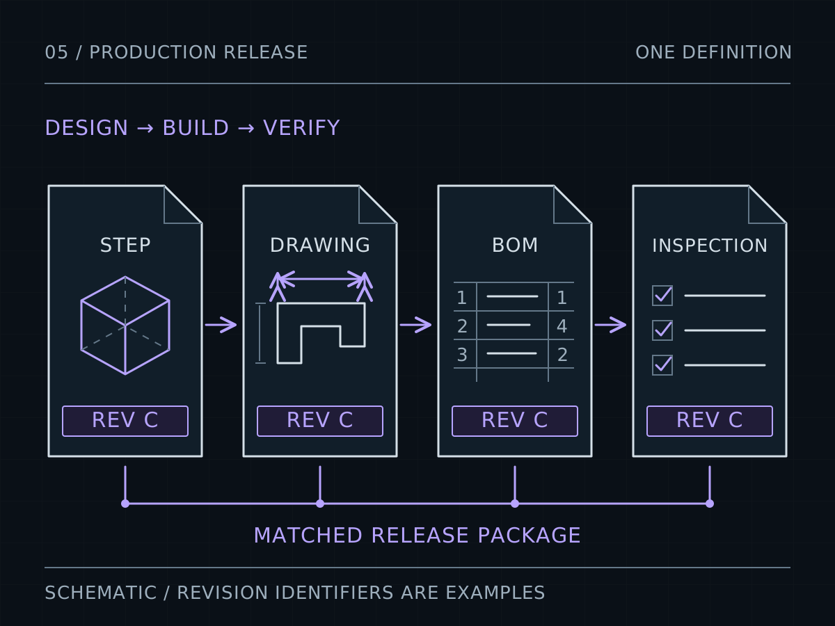
Use component measurements to diagnose the contributors and an assembly check to evaluate the actual function. A successful fit of one prototype does not establish the extremes of a repeat process. Keep the measurements tied to the part revision and retain the observed values, rather than recording only a pass mark.
- Identify the functional gap and its minimum and maximum allowed values.
- Trace the signed dimension loop without counting any contributor twice.
- Include the specified finish on each mating surface.
- Check angular, positional, thermal, and form effects separately.
- Define locating features, floating directions, and clamping conditions.
- Agree on an inspection method that evaluates the final interface.
For broader process comparisons, continue with Tolerance follows the process. This assembly analysis is the next step: deciding how much variation the product can actually accept.
Sources & further reading.
Manufacturer data and technical references support the principles above. Worked scenarios are illustrative design studies. Confirm product-specific requirements against the selected material, hardware, and manufacturing route.
- MIT OpenCourseWare — Tolerance Design
Worst-case and statistical tolerance analysis. The cartridge example is an original hypothetical calculation.
- NIST — Combining uncertainty components
Sensitivity and covariance in uncertainty propagation; measurement uncertainty is distinct from manufacturing variation.
Connect this decision to the next.
Bring the interface into the quote.
Include your model, drawing, material, finish, and the dimensions that control the assembly.
Start a quote ↗