Precision hole prep Xeon NC · Sheet metal
+ Inside the processA clean seat. A flush finish.
Standard inch seat 82°
Metric seat 90°
Inch fastener range #4–¼ in 100° seats available on request. See specifications for thickness and geometry requirements.
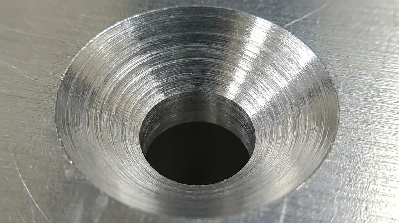
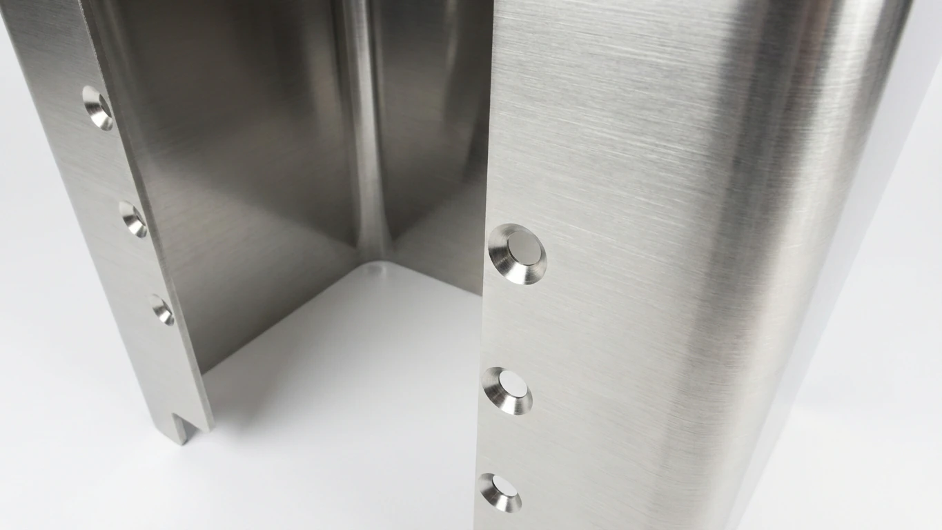
A clean seat. Controlled depth stops keep the seat consistent from hole to hole, with the countersink centered on the pilot hole.
±0.003″ Standard depth tolerance
Depth control: ±0.003″ — consistent seat across every hole in the partConcentricity: CS axis aligned to pilot hole within 0.002″ TIRSurface finish: clean cone walls, no burr at crest or opening Depth control · Concentric seats
Match the seat. Choose the included angle specified for your hardware. Our two standard angles cover inch and metric flat-head screws; 100° seats are available on request.
Standard 82°
Standard inch For standard inch flat-head machine screws, #4-40 through ¼-20.
Standard 90°
Metric For ISO metric flat-head screws, M2.5 through M6.
On request 100°
Wide-angle / rivet For rivets that specify a wider seat. Include the angle in your drawing notes.
The right metal. Countersinking is available across our standard sheet metals. Thickness requirements vary; we review your geometry at quoting.
Aluminum 5052-H32 & 6061-T6 — ideal, clean walls, no burrSteel A1008 & A36 — full range of sizes, slight burr clearance addedStainless 304 & 316 — available, tool-wear managed in-houseBrass & Copper — available on request; specify on drawingMinimum recommended material thickness: 2× fastener head height
Material thickness · Fastener fit
Design with Review seat angles, thickness, and file requirements before quoting your part. Include any special requirements with your drawing.
Angles Available 82° (standard inch), 90° (metric), 100° (wide/rivet — upon request)
Fastener Size Range #4 through ¼″ (inch) · M2.5 through M6 (metric)
Depth Tolerance ±0.003″ standard · Tighter on request (reviewed per geometry)
Min. Material Thickness Aluminum: 0.063″ minimum · Steel/Stainless: 0.060″ minimum
Compatible Materials Aluminum 5052/6061 · Steel A1008/A36 · Stainless 304/316 · Brass (request)
Max Holes per Part No hard limit — large quantities handled on standard run time
File Requirements Mark CS holes in DXF with diameter + angle note, or call out on drawing. We can also follow a hole chart.
Lead Time Same as base order — countersinking adds no lead time to standard 3–5 day production
Call it out. Make the seat diameter, angle, and side clear in your file and drawing.
Mark CS diameter in DXF: draw the countersink as its maximum diameter at the surface — not the pilot hole diameterAdd a note: include angle (82° or 90°) and fastener size in drawing notes or a hole tableCheck material thickness: flag any holes in material thinner than 0.063″ — we'll review those at quotingEdge distance: keep CS center ≥ 2× major diameter from any part edge to avoid breakoutStack-ups: if countersinking both sides, note it explicitly — the default is single-side onlyPost-anodize: anodize after countersinking; Type II coating adds ~0.0002″ and will not affect seating Diameter · Angle · Countersink side
Find your alloy. Each thickness shows the largest flat head that leaves land under the cone and the angle it uses. Select a gauge for its full material specifications.
Dashed chips are below the minimum thickness: 0.063″ aluminum · 0.060″ steel and stainless.
Your next part starts here Finish flush. Upload your part file and call out the countersink holes, seat angles, and fastener sizes for your assembly.
Quote your parts ↗