Enter the two diameters shown above. Locate the sketch point, check the start face and direction, and verify the part selected in Merge scope.
DRAWING CALLOUT / ONE HOLE
Identify top/bottom in a drawing view. Add location and functional tolerances before release.
D = countersink diameter · d = through-hole diameter · θ = included angle Depth = (D − d) / [2 tan(θ / 2)]. Calculated at full precision from Xeon’s diameters; chart depths are rounded. Passing the land check does not guarantee flushness or strength. Confirm the actual fastener, thickness variation, tolerances, and finish.
DESIGN NOTES
From the model to the shop.
02 / How to Read It
Four dimensions. One seat.
The diagram is a slice through the hole. Everything you dimension on a drawing is on that slice.
THE FOUR CALLOUTSMATCH THE DRAWING
ANGLE
Included angle of the cone. Xeon’s inch table uses 82° and its metric table uses 90°. Verify the actual fastener specification.
82° or 90°
OUTER Ø
Major diameter at the sheet surface. Dimension this on the finished-part drawing. Do not cut the major diameter straight through when the laser profile should use the smaller bore.
Major
HOLE Ø
Through-hole under the cone — the pilot the screw shank clears. Laser-cut, then the cone is milled on it.
Minor
THICKNESS
Sheet gauge. Depth is taken from this face. What is left under the cone is the land. Keep at least 0.010″.
Land ≥ 0.010″
03 / 82° vs 90°
Match the fastener, not the CAD default.
A 90° screw in an 82° seat bears on a ring. An 82° screw in a 90° seat does the same. Mismatched angles can cause poor seating and concentrated contact.
Use 82°
Inch flat-head screws
ANSI/ASME B18.6.3 — #4-40 through 5/16
Most US enclosure, rack, and audio hardware
Default at Xeon NC unless the drawing says 90°
Use 90°
Metric flat-head screws
DIN 965 / ISO 10642 — M2 through M8
Check the specified metric fastener’s head geometry
Shallower cone than 82° at the same outer diameter
We do not run 100° or 120° as standard tools.Those angles show up as CAD defaults and as rivet seats. If the model is 100° or 118° (a drill point), it will not match a tool. Match the fastener and available tooling; ask Xeon about nonstandard angles before ordering.
04 / Top or Bottom
The cone can open on either face.
Top is the default: the seat is on the cosmetic or mating face as the part sits in the nested sheet. Bottom puts the same cone on the opposite face so a screw can enter from the back of a panel.
The laser still cuts a square through-hole. The mill then plunges the cone from the selected side. Mark the face in the CAD feature and in the hole table — a countersink on the wrong side is a scrapped cosmetic panel.
Formed parts.Countersinks are milled while the blank is flat, before the brake. If a hole sits on a flange that will stand up, decide now whether “top” is the outside of the box or the inside. The calculator side toggle is that decision.
05 / Call It Out
One hole note. No conflicting depths.
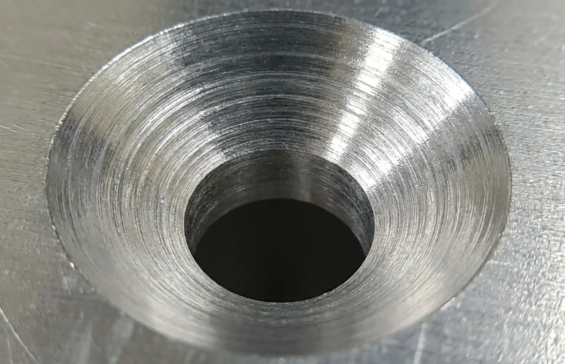
Give the mill a through-hole, an outer diameter, an angle, and a side. Depth follows from the diameters and included angle. Mark a displayed derived depth as reference to avoid conflicting requirements.
01
Use an Onshape Hole feature.
Use the minor from the calculator as the laser hole. Choose Countersink, enter the bore and major diameters, and set Through all with the selected included angle.
0.193 THRU, CSK 0.359 × 82°
02
Name the side.
NEAR SIDE or FAR SIDE, or TOP / BOTTOM as the part is nested. If the cosmetic face is film-side, say so.
03
Keep 0.010″ of land.
If the calculator shows a warning or a fail, drop a screw size or go up a gauge. A thin remaining ring can deform or burr; review a different fastener or thicker stock.
 ← All calculators