Clearance is total.
Slot length = tab width + C. Narrow opening = tab thickness + C. With the tab centered, each opposing side has C/2. Kerf compensation belongs to the cutting toolpath; do not add the beam width again.
 ← All calculators
Xeon NC / Engineering toolsSlot & Tab Sizes
Scroll to exploreMake room for a good fit.
Set the tab, size the opening, and see what needs a closer look before cutting.
Build your joint ↘Powered by Xeon NC
01 / Tab + clearance = opening
Select the tab material and nominal thickness. The result is a starting CAD opening; actual cut tolerance, stock thickness, and finish determine the fit.
Nominal slot · length × narrow opening
02 / Modeled in Onshape
Two tabs locate an upright in a receiving plate. This fixed example uses 0.063″ stock, 0.250″ tab widths, and 0.014″ total clearance.
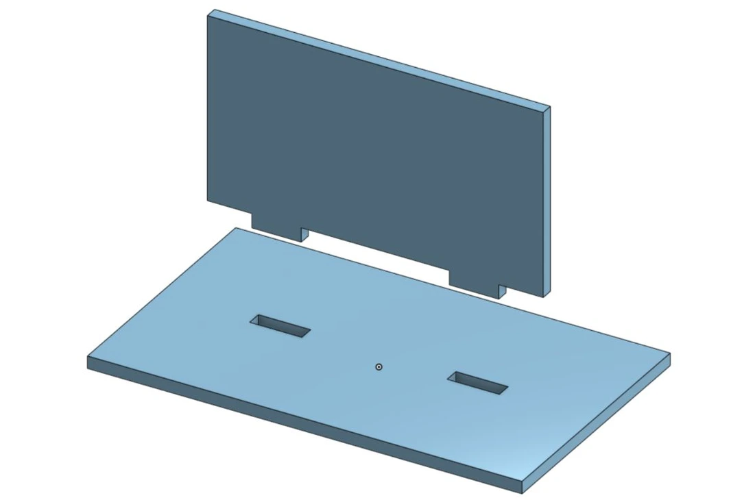
The 0.077″ narrow opening falls below the general 0.0945″ slot screen for this receiver thickness. Treat it as a fit example for process review, not a production-approved cut file. Slot corners are simplified; check the mating corner relief before manufacture.
Open editable Onshape example ↗03 / From the material catalog
Rows use a 2× thickness tab and a receiver of the same thickness. The clearance preset and units follow the calculator above. Select a thickness to load it.
| Stock thickness | Tab width · 2T | Slot length × opening | Total clearance | Narrow-slot screen | Deburring screen | Catalog families |
|---|
Exact thickness is the reference here; gauge names vary by metal. A listed material does not guarantee every feature, fit, finish, or process. Checks flag a review and do not change your nominal opening.
04 / Before you cut
The arithmetic describes nominal geometry. Use actual material and process tolerances to decide how the parts will assemble.
Slot length = tab width + C. Narrow opening = tab thickness + C. With the tab centered, each opposing side has C/2. Kerf compensation belongs to the cutting toolpath; do not add the beam width again.
The close preset uses 0.0075″ total; slide uses 0.0150″. The Xeon baseline uses the existing DFM allowance of assumed kerf + 0.004″. These are planning presets, not fit tolerances or guarantees of a press fit.
Measure the tab from its shoulder. To pass through the receiver, length equals receiver thickness plus the chosen protrusion. Flush, recessed, and proud weld details serve different purposes; a universal 3× thickness rule does not define them.
Xeon’s general DFM screen is max(1.5× receiver thickness, 0.020″). Many close-fitting tab slots fall below it and need process review. The 0.125″ deburring screen also applies to the shorter opening, even when the slot is long.
A large internal slot radius can block a square tab. Coordinate tab chamfers, corner radii, or relief notches on both parts. Keep the nominal length and width and the local relief dimensions separate.
Stock thickness variation, cut tolerance, burrs, coatings, and assembly order can consume the gap. Validate a sample joint with the intended finish before committing to a batch.
Xeon reference inputs: DFM preflight, laser design guide, and deburring limits. Fit and tolerance background: SendCutSend’s tab-and-slot guidance. Different fabricators use different process limits.
05 / Common questions
A slot sized closely around sheet thickness may be narrower than the general 1.5× receiver-thickness screen. The calculator shows that conflict instead of assuming a tab slot is exempt. Xeon can review the feature and cutting process.
The nominal geometry model uses dimensions, not alloy. Real fit depends on the alloy’s stock tolerances, cutting behavior, surface condition, and finish. Material selection limits the nominal thickness options to the catalog.
No. The preset leaves positive nominal clearance. An interference fit needs its own tolerance design and testing; it cannot be guaranteed by these presets.
The Onshape views show a fixed, editable example with dimensions listed beside it. The plan-view diagram in the calculator updates live. Use “Use these dimensions” to load the CAD example into the calculator.