CNC
bending.
From flat patterns to formed parts. Precision press brake bending for brackets, enclosures, and assemblies, built around your material and geometry.
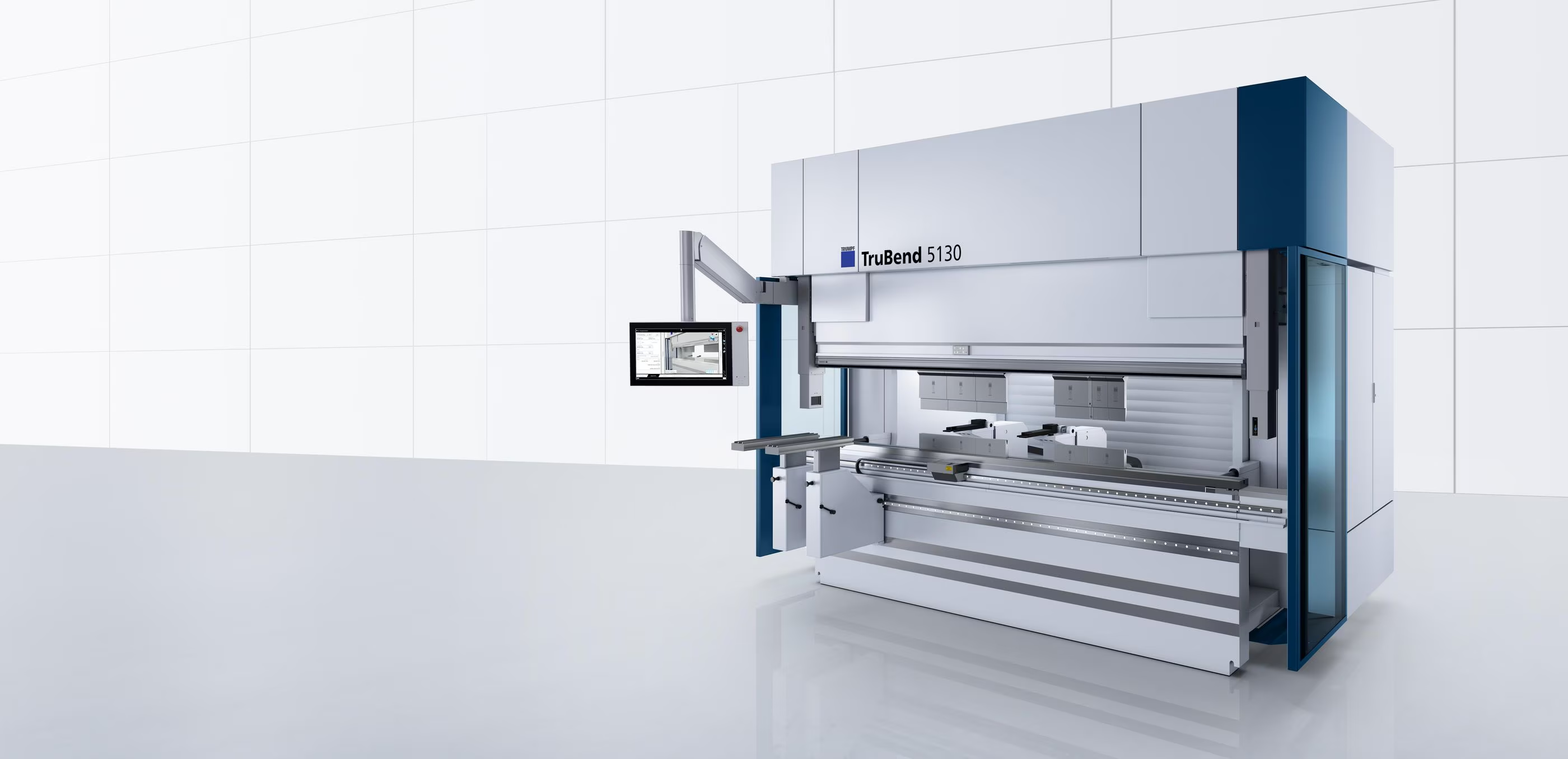
Flat sheet. Formed to fit.
- Angle tolerance
- ±0.5°
- Maximum bend length
- 120 in*
- Part positioning
- 6-axis
* See specifications below for material, geometry, and process limitations.
Angles that
bring it together.
Repeatable bends start with controlled positioning and an understanding of the material. Our CNC press brakes help translate your flat pattern into a part that fits the assembly.
Tolerance depends on the material, grain direction, flange length, and geometry. Call out critical angles in your drawing.
Understand springback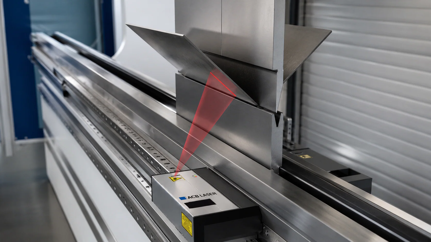
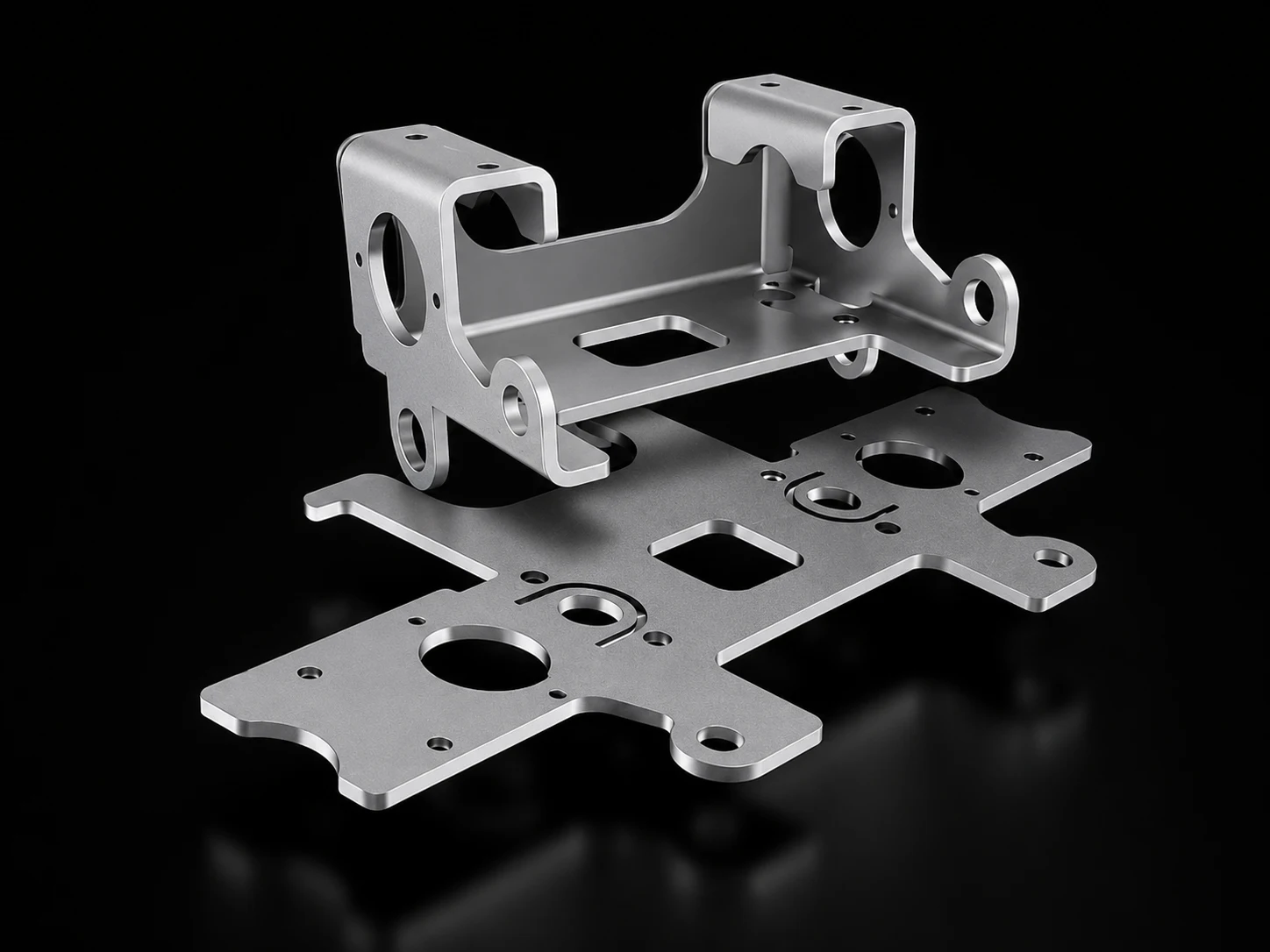
From flat blank.
To finished form.
Laser cutting and CNC bending on the same production floor. Coordinate holes, flanges, and bend lines from the start to keep your design moving.
- Aluminum
- 5052-H32 and other formable stock, selected by thickness and tooling.
- Steel & stainless
- Carbon steel, 304, and 316 options for brackets and enclosures.
- Specialty requirements
- Ask us to review copper straps, busbars, and other forming applications.
Design with
the details.
Start with these process guidelines. Include critical dimensions, material requirements, and finish expectations with your quote.
- Angle tolerance
- ±0.5° standard Depends on material grain, flange length, and part geometry.
- Bending process
- V-die air bending Bend angles from 30° to 135°. Review tooling access for multi-bend parts.
- Maximum bend length
- Up to 120″ Subject to material thickness and tonnage requirements.
- Minimum flange & radius
- Check the selected material and gauge The lookup below shows the tooling-specific values for your stock.
- CAD workflow
- STEP models or DXF flat patterns Include bend line indicators and critical dimensions.
- Tooling & measurement
- 6-axis backgauge · I-axis · ACB Laser Positioning, lower-die shifting, and in-process angle measurement.
Bend data by material.
Select a material and thickness for its tooling assignment, K-factor, inside radius, minimum flange, and bend deductions. These are air-bending reference values; verify production flats with a test bend.
K-source identifies the calibrated material family used for the calculation. Where direct data is unavailable, the lookup uses a related family and shows its notes. Tooling values reference the 5-die TRUMPF set.
Six axes.
One consistent setup.
Independent X1/X2, R1/R2, and Z1/Z2 positioning lets the backgauge locate the part for each bend.
This supports tapered flanges, asymmetric profiles, and progressive bend sequences without relying on one fixed stop position.
Tooling that
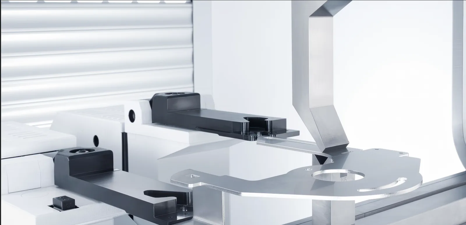
moves with the job.
The I-axis shifts the lower die to support transitions between forming operations.
Hemming, offsets, and specialty profiles depend on the tooling and available access. Review these features early when planning the bend sequence.
Explore the tooling library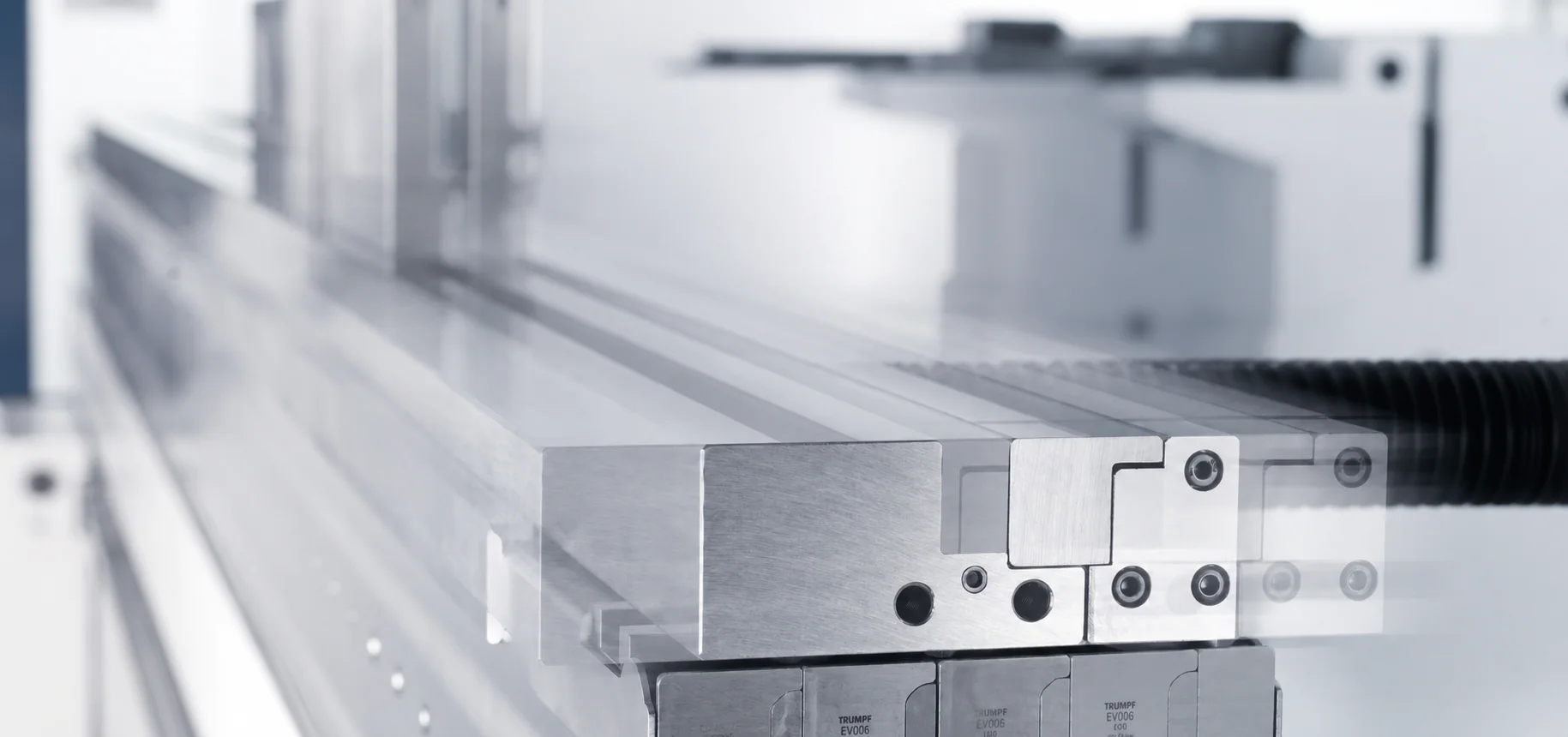
Measure the angle.
Account for springback.
Automatically Controlled Bending uses laser measurement to track the angle during forming and help compensate for springback.
The system adjusts the pressing stroke to account for variations in the material, supporting consistent angles across the run.
Read the ACB Laser guide
The right sheet.
The right tooling.
Each thickness lists its die opening and minimum flange. Open the material for full specifications, or use the bend data lookup above.
Browse the sheet metal catalog for stock and bending specifications.
Bring your
next bend to life.
Upload your part file, specify the material, and include the angles and dimensions that matter to your assembly.
Quote your parts