Shape is only part of the story
Design the part.
Consider the forming path.
A clean folded model describes the result. It does not automatically prove that every flange can be supported, located, bent, and removed from the tool.
Start with the exact alloy, temper, thickness, and finished dimensions. Then work through the part one bend at a time. A short flange, a nearby cutout, or an earlier bend can change what the next operation needs.
This guide uses original comparison models to make those constraints visible. Use the complete bending guidelines for the overall workflow, and the linked material and tooling guides for the values that apply to your part.
Tapered mounting ear
Support the whole flange.
The shortest supported area matters more than the longest flange dimension.
The problem
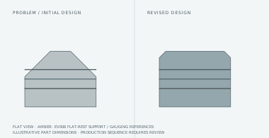
The tapered ends stop short of the EV006 shoulder boundary while the middle of the flange still reaches across it. The flat blank therefore loses support at the ends even though its center flange dimension looks generous.
The design change
Move the taper beyond the support region. The revised outline keeps the full-width edge across the die shoulders. Recheck that outline whenever the die opening, bend location, or material changes.
What to check. Inspect the complete flange outline in the flat view. Compare its shortest effective reach with the minimum flange for the selected material, thickness, angle, and die. A taper, notch, or curved end can be the controlling feature.
Inside the Onshape example
Example 1 now includes the OW202/S punch and the EV006 W20/30 R2 die at the flat-rest position. The support references come from the die profile: the horizontal shoulders begin about 11.932 mm either side of its center. Contact changes during bending; these lines describe the starting support condition.
Open the model ↗ · Edit the feature, turn off “Show all eight examples,” and select 1.
Sensor mounting plate
Keep precision features out of the bend zone.
Measure from the nearest feature edge, with a clear reference to the bend.
The problem
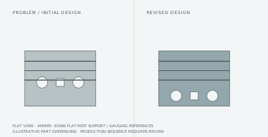
The EV006 near-side shoulder boundary passes through the two holes and slot in the initial blank. The missing material interrupts support close to the bend and puts the sensor’s locating features at risk of distortion.
The design change
Move the pattern toward the plate’s unbent region. The revised holes and slot clear the flat-rest shoulder boundary. Separately check the required distance from each feature edge to the bend using the selected material and tooling.
What to check. Check both hole-to-bend clearance and remaining material along the die-contact region. Do not confuse a center-to-center dimension with edge clearance, or a bend centerline with a bend tangent. Use the reference specified by the applicable Xeon guide.
Inside the Onshape example
Example 2 uses a bend center at y = 45 mm. The near-side flat-rest shoulder reference is at y = 33.068 mm. The initial 14 mm holes span y = 23–37 mm; the revised holes span y = 6–20 mm. Those coordinates explain this model, rather than establish a general hole-spacing rule.
Open the model ↗ · Edit the feature, turn off “Show all eight examples,” and select 2.
Two-flange corner blank
Open the corner before it has to move.
Where bend zones meet or terminate, make the material separation intentional.
The problem
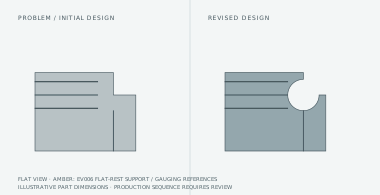
At the re-entrant corner, two bend directions compete for the same material. A full tool profile makes the access question visible, but changing the punch cannot create the missing material separation.
The design change
Open the corner and check both the resulting seam and the available tool length. The revised blank uses a larger circular opening, with a shortened tool segment ending beside it. Confirm the required relief shape and extent for the actual bends.
What to check. Review bend-end relief and corner relief separately. In a native Onshape sheet metal model, the Bend relief feature controls the cut at a bend end; the Corner feature handles the junction. Verify the final opening with the shop instead of treating a CAD default as approved tooling data.
Inside the Onshape example
Example 3 now uses a 14 mm-radius corner opening and a 56 mm-long illustrative tool segment for the first bend. The second bend is marked separately. The OW202/S and EV006 profiles provide setup context; the model does not simulate both bending operations or specify a production relief minimum.
Open the model ↗ · Edit the feature, turn off “Show all eight examples,” and select 3.
Return-flange cover
Check the return against the whole punch.
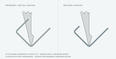
The active bend belongs at the punch tip; the return must clear the body above it.
The problem
The initial 40 mm return intersects the OW202/S body when the part is rotated into the illustrated 90° bending pose. The tip itself fits. The obstruction is farther up the offset body, on the less-relieved side of the tool.
The design change
The 18 mm return ends before reaching that body in the same pose. The comparison changes only the lip length. Flipping the punch in the viewer exposes its asymmetric clearance; it does not approve a new production sequence.
What to check. Inspect the real cross-section in its working orientation, then review approach, overbend, holders, working length, die, and withdrawal. A static pose can demonstrate a body collision or its removal. It cannot establish that the entire stroke and bend order are feasible.
Inside the Onshape example
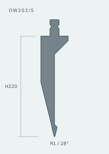
Example 4 uses the actual OW202/S R1 / 28° / H220 profile from Xeon’s DXF, including its curved tip and offset body. The part retains 2 mm walls, 3 mm inside radii, and a 60 × 50 mm section. Its active bend is placed around the tip in a 90° pose, following the approach demonstrated in the reference assembly. The 40 mm tool extrusion is an illustrative segment length.
Open the model ↗ · Edit the feature, turn off “Show all eight examples,” and select 4.
Enclosure corner study
Give neighboring walls a real seam.
A tool-access check and a part-interference check answer different questions.
The problem
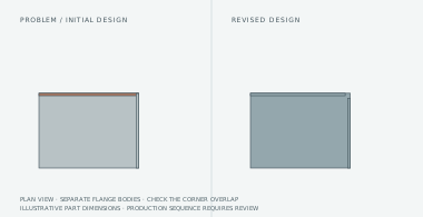
The two flange bodies overlap at the corner by 1.8 × 1.8 × 30 mm in this model. Bringing in the real punch does not resolve a conflict already present in the final part.
The design change
Increase the end setbacks to separate the neighboring walls. The revised study uses a 4 mm end setback, which is different from specifying a 4 mm finished seam gap. Set the production seam from assembly, welding, finish, and tolerance requirements.
What to check. Onshape’s Interference detection can identify overlapping material between selected parts. A clean result at the final angle does not check the intervening motion, overbend for springback, or clearance to tooling. Those need a separate sequence review.
Inside the Onshape example
Example 5 remains a dedicated three-solid corner study so the overlap can be inspected independently of tooling. Its initial overlap is 97.2 mm³; the revised solids have no overlapping volume. Use Onshape Interference detection on the flange bodies, then review forming motion separately. These separate bodies are not an unfoldable sheet metal part.
Open the model ↗ · Edit the feature, turn off “Show all eight examples,” and select 5.
U-channel bracket
Check width and wall height together.
Two individually simple bends can create a difficult second operation.
The problem
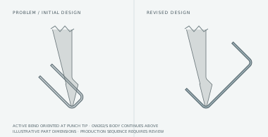
With the second bend located at the OW202/S tip, the tall opposite wall of the narrow channel cuts into the punch profile. The relevant obstruction is the earlier flange during the next operation, rather than a punch drawn vertically inside a finished upright channel.
The design change
Widening the section and shortening its walls moves the earlier flange away from the body in the illustrated pose. Keep the functional opening and mounting surfaces in mind before changing either dimension.
What to check. Review the second bend with the earlier flange already formed. Check the actual punch orientation and its entire section, then the die, overbend, holders, and extraction path. If a different tool or sequence is proposed, repeat the access review for that setup.
Inside the Onshape example
Example 6 places both versions at the same 90° active-bend orientation against the exact OW202/S profile. Outside width changes from 18 to 65 mm and wall height from 45 to 28 mm; thickness stays 2 mm and inside radius 3 mm. The initial section intersects the tool body; the revised section does not in this static pose.
Open the model ↗ · Edit the feature, turn off “Show all eight examples,” and select 6.
Irregular mounting bracket
Give the part a repeatable locating edge.
The part needs a reliable way to register against the backgauge for each operation.

The problem
At the flat-rest setup, the peaked rear edge misses the two 5170S finger shoulders. The lower shoes can support the blank, but repeatable gauging needs contact with both vertical locating faces.
The design change
Add two aligned landing tabs while preserving support over the die. Each tab rests on a finger shoe and meets its locating shoulder at the same distance from the bend. If the tabs will be removed later, define that operation and protect any functional dimensions.
What to check. Review the gauging surface at every step of the sequence. Earlier bends, small notches, and flexible extensions can change which edge is available. The actual finger positions and contact arrangement must match the machine setup.
Inside the CAD example
The website viewer uses the left and right STEP solids from Xeon NC | 5170S Backgauge Fingers | 3x12 RE Estimate, tessellated with OpenCascade. Their 3 × 12 in envelopes, notched tips, rounded bodies, and mounting holes are preserved at full scale. The 2 in height and smaller features are reverse-engineered estimates. The finger spacing and flat-rest placement illustrate contact with this sample blank; they are not a verified machine setup. The enlarged blank is 225 × 187.5 × 2 mm, with 24 mm-wide contact tabs spaced 155 mm center to center. Both locating shoulders are 100 mm behind the bend centerline.
Open the sample blank ↗ · Edit the feature, turn off “Show all eight examples,” and select 7.
Open the 5170S finger models ↗ · The detailed fingers are imported into the website viewer from this separate document.
Springback & overbend
Bend past the angle you want.
The angle under the punch is not the angle after the load comes off.
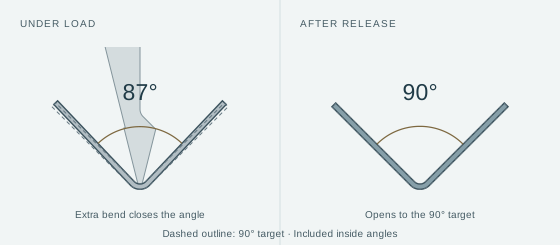
Illustration only. The slider assumes a recovery amount; it does not calculate springback for a material. All angles are included inside angles: a smaller number means a tighter bend.
Why the angle opens
Bending produces both permanent deformation and elastic strain. When the punch releases, the elastic part recovers and the bend opens. Stopping at 90° under load can therefore leave the finished part more open than 90°. SSAB explains this elastic recovery ↗
Why we overbend
Overbend by the amount needed for that setup. In this teaching example, 3° of recovery means closing the inside angle to 87° under load so it opens to 90° after release. Without that compensation, a 90° loaded bend would open to 93°.
Keep the finished intent in your drawing
Model and specify the finished 90° angle. The tighter 87° angle belongs to the forming setup in this example. It is not a replacement for the final part dimension.
What to check. Measure the unloaded part and adjust the bend program for the actual material, thickness, radius, and tooling. Check tool and flange clearance at the tighter loaded angle, too: a part that clears at 90° may collide while overbending. The punch and die must also permit the extra closure. Higher-strength steels and a larger die-opening-to-thickness ratio can increase springback; use the actual setup to establish compensation. See SSAB’s setup guidance ↗
Inside the Onshape example
Example 8 contains an 87° loaded section with the real OW202/S punch and a separate 90° released section without the punch. Both use 2 mm walls, a schematic 3 mm inside radius, 42 mm straight legs, and a 40 mm extrusion. The 3° recovery is illustrative, not a prediction for a particular alloy. The radius is held constant to isolate the angle change; this is not a deformation simulation. The lower die, machine stroke, and springback forces are omitted.
Open the model ↗ · Edit the feature, turn off “Show all eight examples,” and select 8.
From the article to your CAD review
Open the examples.
Follow the geometry.
Part Studio 2 contains the revised eight-case study with real tool profiles. Part Studio 1 and the reference Assembly 1 retain the original examples and the positioned tool. Open the new custom feature to isolate a pair or hide the setup references.
- Open Part Studio 2 and edit Xeon real-tool bending examples 1.
- Turn off Show all eight examples, then select example 1–8.
- Toggle “Show real tool profiles and setup references” to inspect the part itself. Edit the Feature Studio source to explore other dimensions.
Onshape access follows the document’s existing permissions. The part models are illustrative solids, rather than native sheet metal features or production flat patterns. OW202/S curves in the new Feature Studio retain the source DXF arcs; the browser uses a sampled display mesh. The corner example intentionally contains separate overlapping flange bodies.
Your next part
Bring the finished intent.
Send the formed STEP model, material and thickness, and a drawing that identifies functional dimensions. Point out any feature that cannot move so the tooling and sequence review starts with the right priorities.
References & further reading
Original Xeon NC geometry and explanations, alongside the shop’s existing bending guidelines, bend-affected zone guide, and tooling library.
For the CAD checks: Onshape documents Bend relief and Interference detection.