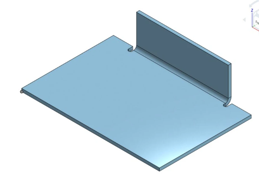
Give the end of the bend a free edge.
A partial flange bends upward while the shoulder beside it stays flat. The material at that transition cannot follow both shapes freely. A relief cut separates those regions so the bend can form without dragging the shoulder along with it.
Without the required relief, the surrounding material deforms.
When a bend stops beside flat material, leaving out the relief keeps the moving flange connected to the shoulder that is supposed to stay flat. As the flange bends, it pulls on that connection. The shoulder can lift or twist, the edge can bulge, and the material at the end of the bend can stretch or tear. That unwanted deformation can change the finished dimensions and prevent the part from sitting flat or fitting its mating part.
A properly sized relief gives the flange a free edge at that transition, reducing the pull on the surrounding sheet. A slot that is too narrow or too shallow may still leave material in the bend region and allow distortion.
This applies where relief is needed. A full-width bend that reaches two free outside edges, like example 03 below, has no adjacent flat shoulders to separate. Inspect both ends of every bend rather than adding slots to every flange. The Onshape images show the intended geometry; they do not simulate the bulging or tearing that can occur during forming.
Bend relief and corner relief solve different details.
Bend relief addresses the end of a bend beside unbent material. Corner relief addresses the meeting point of multiple bends, such as two walls of a tray. A part may need both. See our six-example corner-relief guide for that comparison.
One plate. Three bend terminations.
These examples were modeled in Onshape and captured as screenshots for this article. Each comparison shows the formed part beside its flat pattern. The images show nominal CAD geometry, not a physical forming test or a simulation of tearing.
| Setting | Value | What it controls |
|---|---|---|
| Base sketch | 6 × 4 | The rectangle used to create the base sheet |
| Thickness / inside radius | 0.125 / 0.125 | Sheet thickness and nominal bend curvature |
| Flange distance / bend angle | 1.5 / 90° | Flange feature inputs, with Inner alignment |
| Partial flange bounds | 1.0 at each end | Flat shoulders retained in examples 01 and 02 |
| Relief width / depth scales | 1.25 / 1.5 | Dimensionless multipliers in examples 01 and 02 |
| Default bend K factor / Minimal gap | 0.40 / 0.020 | Model parameters; Minimal gap is a separate rip setting |
These are demonstration inputs, not a Xeon material specification or an approved minimum relief. No material grade is assigned as a production requirement in these examples.
Obround relief
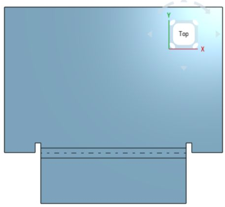
The flange stops 1 inch short of each end of the selected edge. At both transitions, a rounded slot separates the bend from the flat shoulder. In the blank, follow the slot past the two solid bend-boundary lines; the dashed line between them marks the bend center.
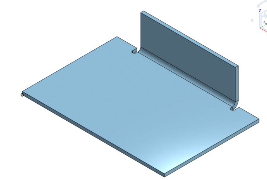
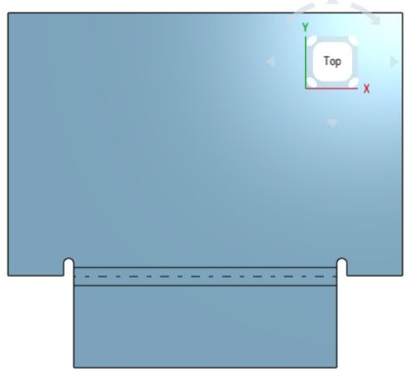
Why choose it
A rounded end avoids a sharp re-entrant corner at the bottom of the slot. It is a useful starting geometry when the opening must stay compact.
What to check
Keep the slot wide enough to cut and deep enough to clear the bend region. A rounded slot is still a notch in the load path; it does not establish fatigue strength.
Rectangular relief
This Part Studio duplicates the first plate and changes only Bend relief type to Rectangle – Scaled. Thickness, bend radius, flange settings, and both relief scales stay the same. The flat pattern makes the square-ended slot easiest to recognize.
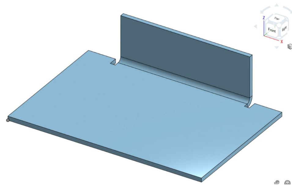
Why choose it
Straight slot walls and a flat end make the outline easy to dimension and inspect. Compare the cut boundary with the obround before choosing a detail.
What to check
The internal corners are sharper than the obround’s rounded end. Review notch sensitivity when the area carries repeated loading, and inspect cut quality and edge condition.
Full-width flange
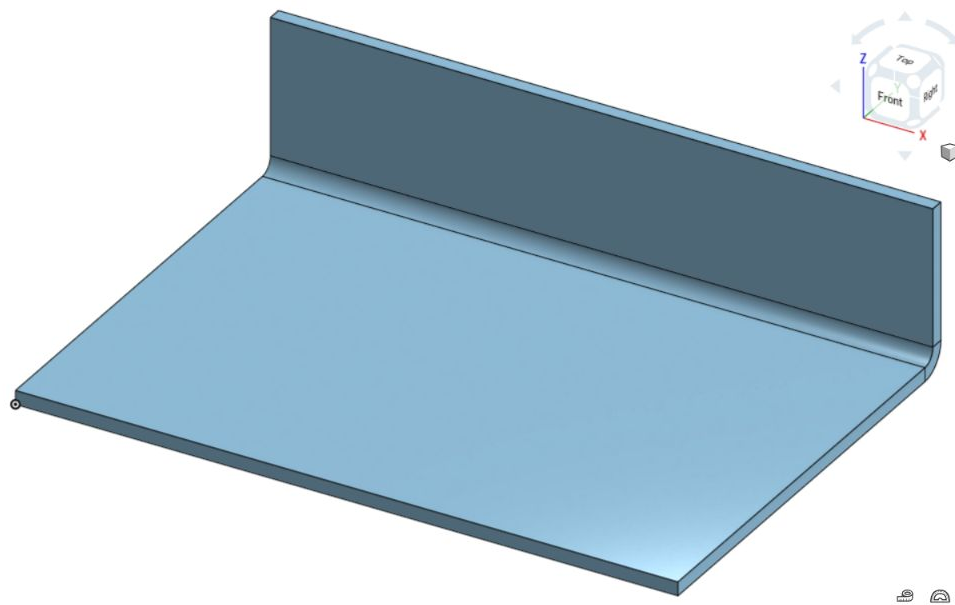
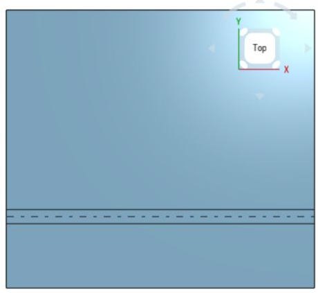
In the third model, Partial flange is switched off. The flange spans the entire 6-inch edge, so both ends of the bend meet free outside edges. There is no adjacent flat shoulder to isolate, and Onshape produces a straight-sided blank without the two relief slots.
Why choose it
When the design permits it, extending the flange to a free edge can eliminate a bend termination inside the sheet. This also removes two small features from the cut outline.
What to check
This example changes the flange width and footprint. It is not a drop-in replacement if the flat shoulders serve a purpose. Edge deformation and tooling access still need review.
Check width and depth separately.
Width is the opening across the slot. It must be compatible with the cutting process and the local forming geometry. A zero-width line is not an adequately defined slot. Depth determines how far the cut reaches into the sheet; check it against the bend boundaries in the flat pattern, not only the centerline.
Thickness × width scale. The two partial-flange examples use this nominal slot width.
Onshape defines its depth scale relative to the bend geometry. A scale of 1 corresponds to its baseline relief touching the bend; additional depth is calculated as (depth scale − 1) × bend radius. In this example, (1.5 − 1) × 0.125 = 0.0625 inch of additional depth. That value is not the total slot length. Onshape documents both scale definitions.
A rule written from the bend centerline, a tangent line, or the original sheet edge uses a different reference. Before copying any dimension into CAD, identify its reference and measure the resulting cutout in the flat pattern. Larger reliefs also remove more load-bearing material and leave a larger visible opening after forming.
Use the bend data for the material you will order.
Choose the material and thickness in Xeon’s material catalog, then use the applicable bend radius and bend-development data. Recheck the relief after changing either. If the required cut width or relief depth is not specified for your process, have the detail reviewed before release.
Build the relief into the sheet-metal model.
- Create the base. Sketch a 6 × 4-inch rectangle on the Top plane. Use Sheet metal model → Thicken and select the sketch region.
- Set the demonstration geometry. Enter 0.125-inch thickness and 0.125-inch inside radius. Under Material, the examples use a default bend K factor of 0.40.
- Set the relief defaults. Expand Relief. Choose Obround – Scaled, depth scale 1.5, and width scale 1.25. Minimal gap is 0.020 inch; it is a separate control from slot width.
- Add the partial flange. Select a 6-inch edge. Use Inner alignment, Blind distance 1.5 inches, and a 90° bend angle. Enable Partial flange with a 1-inch bound at each end; keep Hold adjacent edges enabled.
- Inspect both views. Open Sheet metal table and flat view. Locate each slot, the bend boundaries, and the flat shoulders. Confirm the model regenerates and the intended cut outline is continuous.
- Compare one change at a time. Duplicate the Part Studio. Change the relief type to Rectangle – Scaled for example 02. In another duplicate, disable Partial flange for example 03.
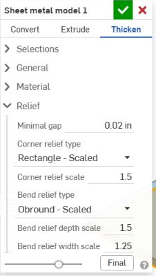
The dedicated Bend relief feature can override a selected relief locally and offers sized as well as scaled options. Use the relevant edge or vertex selection and inspect the result in the flat view. The three models above use the defaults in Sheet metal model. See Onshape’s Bend relief reference.
For more on the flange bounds, see Onshape’s partial-flange walkthrough.
A clean CAD view is only the first check.
| Mistake | What to check instead |
|---|---|
| Inspecting only the folded part | Open the flat pattern and follow the cut around both ends of the bend. |
| Treating a scale as inches | Calculate the width and measure the actual depth from a named reference. |
| Using Minimal gap to size the slot | Edit bend-relief width and depth; rip clearance is a different parameter. |
| Choosing Tear to hide the opening | Evaluate the actual manufactured cut and forming behavior. A clean nominal seam does not prove a usable relief. |
| Keeping demo settings after changing material | Update the bend geometry for the chosen process, then review the cutout again. |
| Adding relief beside a critical hole without review | Check the remaining ligament and hole-to-bend distance. See the hole placement guide. |
Before you send the part to be cut.
- Confirm the material, thickness, inside radius, and bend-development inputs.
- Inspect both ends of every bend, including short flanges and internal tabs.
- Verify real relief width and depth in the flat pattern against the cutting and forming requirements.
- Review the remaining material around slots, holes, fasteners, and loaded sections.
- Check tooling access, flange support, and bend sequence; successful CAD regeneration does not validate these.
- Export the current formed model and any requested flat pattern or drawing from the same revision. Follow the Onshape STEP export guide.
Examples and references
The screenshots were captured directly from the Onshape models created for this guide on September 5, 2026. Formed views, flat patterns, and the relief-settings panel are reproduced above.
CAD control definitions: Sheet Metal Model and Sheet Metal Bend Relief. Further reading: SendCutSend’s bend-relief guide. Its service-specific manufacturing limits should not be read as Xeon specifications.