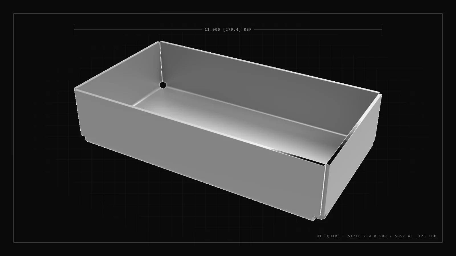
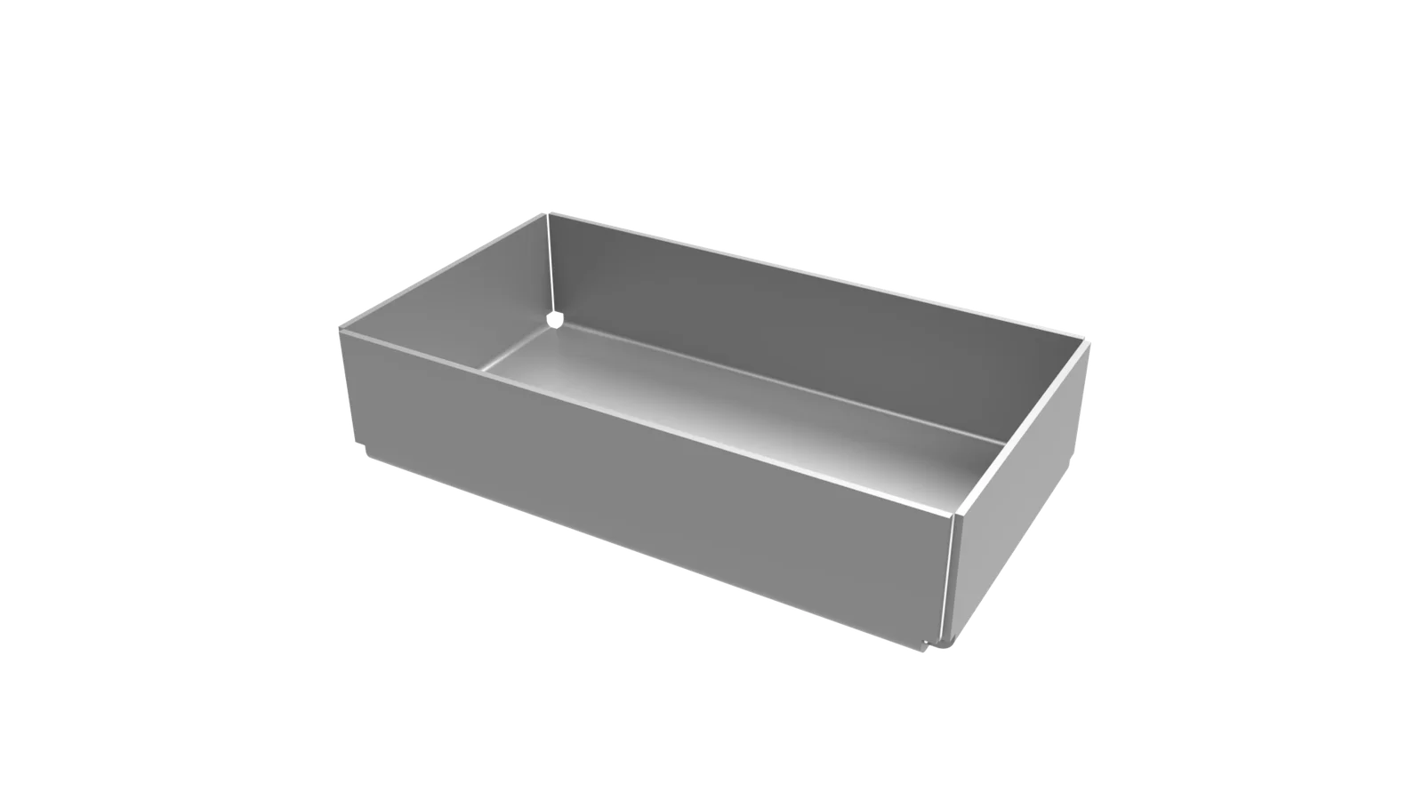
One 11 × 6 × 2.5″ box in 0.125″ 5052 aluminum, modeled six times with a different Onshape corner relief each time. Formed corner and flat pattern side by side, on drawing sheets, so the differences are easy to see before you pick one. Then the Xeon NC numbers that turn the demo into a part.
Design Guide / Box Corners12 minute read
CORNER RELIEF / 01 SQUARE - SIZED
Types compared
6
Test box
11 × 6 × 2.5″
Material
5052 AL .125
Relief dimensions
PART-SPECIFIC
2 SIZED
Explicit width or diameter
Square - Sized and Round - Sized. You type the opening. It stays that size on every gauge.
2 SCALED
A multiplier, not a length
Rectangle - Scaled and Round - Scaled. The opening follows the bend geometry. 1.5 is not 1.5 inches.
2 TYPES
Closed and Simple
These retain more corner material in this example. Check both seam clearance and the bend intersection.
NOT BEND RELIEF
A different tool
Bend relief stops tearing where one bend dies into sheet. Corner relief is where two bends meet.
Corner relief is the material you remove from the flat pattern where two bends meet at a box corner. Without it, the two bend regions overlap and the walls collide, tear, or bulge as they fold up. Onshape offers six ways to cut that corner, and they sort into three pairs: two sized cutouts, two scaled cutouts, and two corner treatments that retain more material in this example.
The choice depends on both the bend geometry and the corner’s intended use. An open-seamed tray can take a large, easy-to-inspect square. A welded enclosure may benefit from a close-fitting corner, provided it can be formed and meets the welding procedure. Simple can be a useful baseline, but needs the same forming checks. Decide open, welded, or sealed before you decide square, round, or closed.
A relief that looks right in the folded view is proved in the flat pattern.
SIX TYPES / SHEET METAL MODEL › RELIEFONE BOX
01 SQUARE
Square - Sized. A square cutout of a stated width. Straight sides, easy to inspect. The reference the others are compared against.
Sized
02 RECT
Rectangle - Scaled. A rectangular cutout whose size is a multiplier of the local bend geometry rather than a fixed width.
Scaled
03 ROUND
Round - Sized. A circular cutout of a stated diameter. Smooth boundary, no sharp re-entrant corners.
Sized
04 ROUND
Round - Scaled. A circular cutout that follows the bend geometry. Larger than the fixed 0.500″ round on this box.
Scaled
05 CLOSED
Closed. The large opening disappears. The walls meet closely at the base and much more material stays at the corner.
Rip
06 SIMPLE
Simple. Onshape’s basic treatment. A small opening remains, with a simpler notch than the enlarged reliefs.
Rip
What this guide is, and is not.The screenshots and the regeneration observations come from an Onshape model study. The uses and cautions are engineering interpretations. No physical bending, welding, leak test, or stress analysis was performed. Catalog bend data is shown for reference; no corner-relief production limit was validated. See our material page and the corner flange collision guide.
02 / The Test Box
One box, held constant.
Every example is the same four-wall box. The four walls use 90° bends and all four corners share the selected relief type, so the only thing that changes from sheet to sheet is the corner.
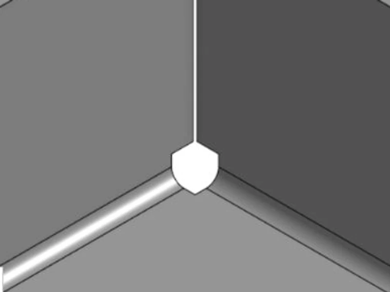
The test box11.000″ long, 6.000″ wide, 2.500″ tall outside, 0.125″ sheet. Shown here with 01 Square - Sized at 0.500″. The small notch at the top of each vertical seam is the relief seen from above.
Outside length11.000 in
Outside width6.000 in
Outside height2.500 in
Sheet thickness0.125 in
Material libraryAluminum - 5052
Inside bend radius0.125 in
Bend K factor0.4
Minimal gap0.020 in
The orange values are demonstration inputs.Radius, K factor, minimal gap, and relief sizes were chosen to make the six types easy to tell apart, not to match a press brake. Assigning a material from the Onshape library does not calibrate the sheet-metal bend settings. Before you cut, replace them with the temper, tooling, and bend data for the shop that will form the part. Section 08 does that for Xeon NC.
03 / The Six Sheets
Formed corner, flat pattern, tradeoffs.
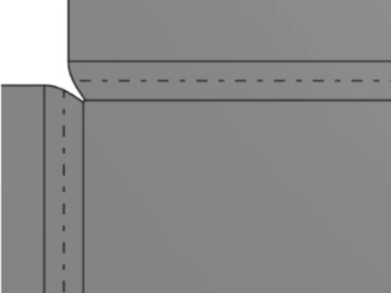
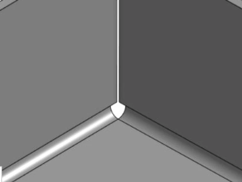
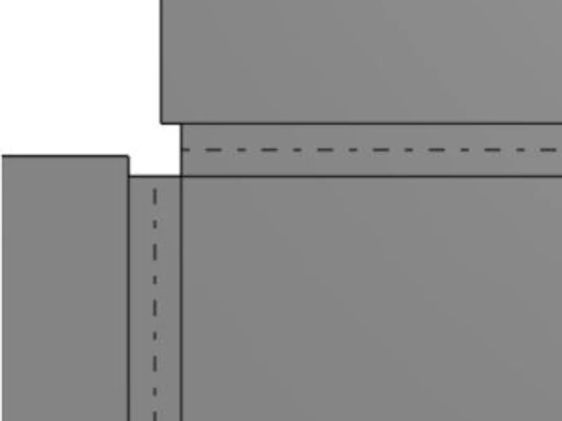
Each type gets its own drawing sheet. View A is the folded corner looking down into the box. View B is the same corner on the flat pattern, where the bend centerlines are dashed and the relief is the white cutout. Read the flat pattern; that is what the laser cuts.
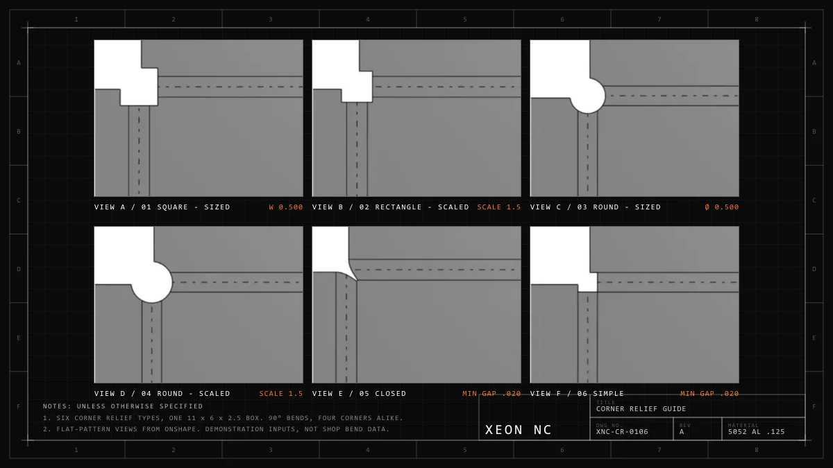
Index sheetAll six flat-pattern corners at the same magnification. The two scaled reliefs (B and D) are visibly larger than their sized counterparts (A and C) at these inputs. Closed (E) and Simple (F) leave no cutout, only a rip.
123456
123456
ABCD
ABCD
01 / Corner relief / Sized
Square - Sized
Width 0.500 in
A square cutout in the blank becomes a curved-looking opening after the walls are bent.
Corner relief width 0.500 REF
View A / Formed cornerOnshape
View B / Flat patternTop
Good for
Use when you want an explicit relief width and a straight-sided cutout that is easy to inspect in the flat pattern. It is a useful reference against the scaled rectangle.
Things to watch
Sharp internal cut corners can concentrate stress. Deburr the cut and inspect for tearing or bulging after forming. On this model, 0.250 in produced a relief-too-small warning; 0.500 in regenerated successfully. That is a CAD result, not a universal minimum.
Notes: unless otherwise specified1. Crops from actual Onshape screenshots. 2. Uses and tradeoffs are design guidance, not a forming test.
The cutout is rectangular and its size is controlled by a scale rather than a fixed width.
Corner relief scale 1.5 (dimensionless)
View A / Formed cornerOnshape
View B / Flat patternTop
Good for
Useful for related sheet-metal designs where you want the relief to respond to the local bend geometry. It avoids prescribing one fixed opening size for every thickness and radius combination.
Things to watch
A scale of 1.5 is dimensionless; it is not 1.5 inches. Recheck the actual opening whenever thickness or bend geometry changes. On this symmetric box, the shape can look nearly square. Check the flat pattern rather than judging only the folded view.
Notes: unless otherwise specified1. Crops from actual Onshape screenshots. 2. Uses and tradeoffs are design guidance, not a forming test.
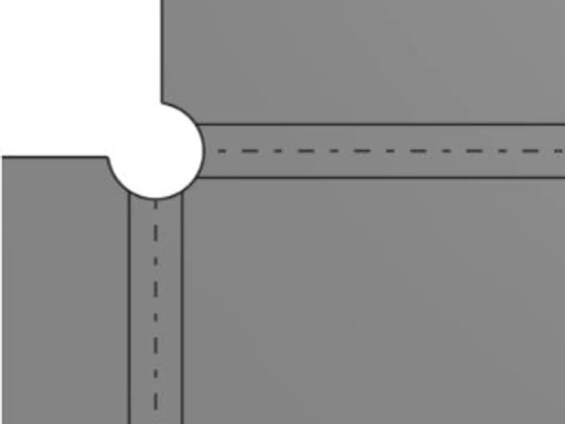
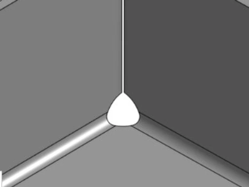
The circular boundary is easiest to recognize in the flat pattern on the right.
Corner relief ø 0.500 REF
View A / Formed cornerOnshape
View B / Flat patternTop
Good for
A candidate when you want a smooth cut boundary and an explicit diameter. A rounded boundary avoids the sharp re-entrant corners of a square cutout. This is a useful starting comparison for a fabricated tray.
Things to watch
The diameter still has to clear the intersecting bend regions. A large round opening removes material and may require more weld fill or a different sealing detail. Smooth geometry alone does not establish fatigue strength or guarantee crack-free bending.
Notes: unless otherwise specified1. Crops from actual Onshape screenshots. 2. Uses and tradeoffs are design guidance, not a forming test.
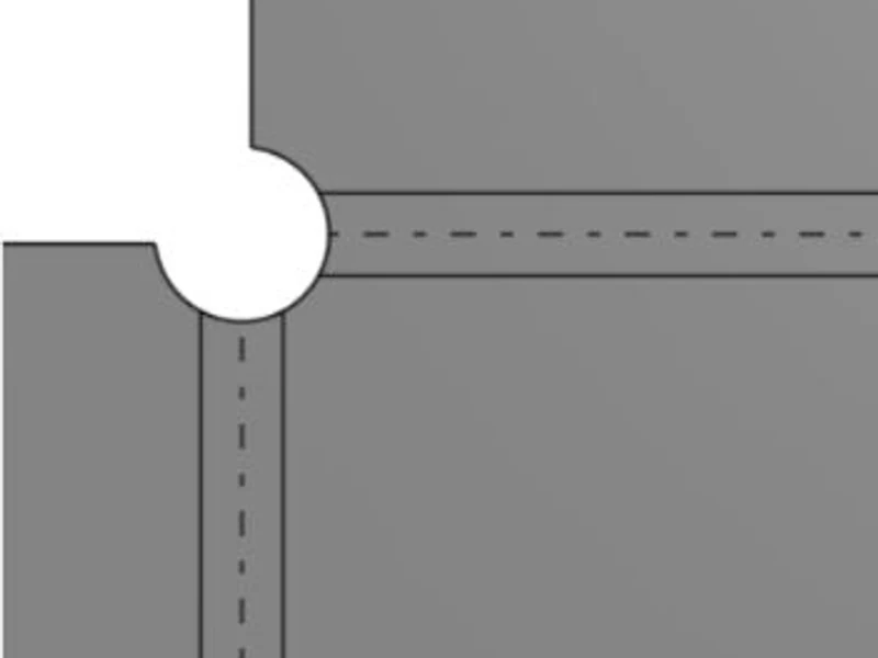
The rounded opening is larger here than the fixed 0.500-inch round example.
Corner relief scale 1.5 (dimensionless)
View A / Formed cornerOnshape
View B / Flat patternTop
Good for
Useful when you prefer a rounded opening that adapts to the bend geometry. Compare it with Round - Sized to decide whether a fixed diameter or automatic scaling better fits your drawing and inspection process.
Things to watch
Matching the rectangle scale does not mean matching its opening area or width. Measure the resulting relief in the flat pattern. A larger opening can improve clearance but leaves less material and can make a closed, welded corner harder to finish.
Notes: unless otherwise specified1. Crops from actual Onshape screenshots. 2. Uses and tradeoffs are design guidance, not a forming test.
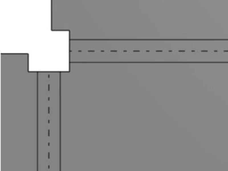
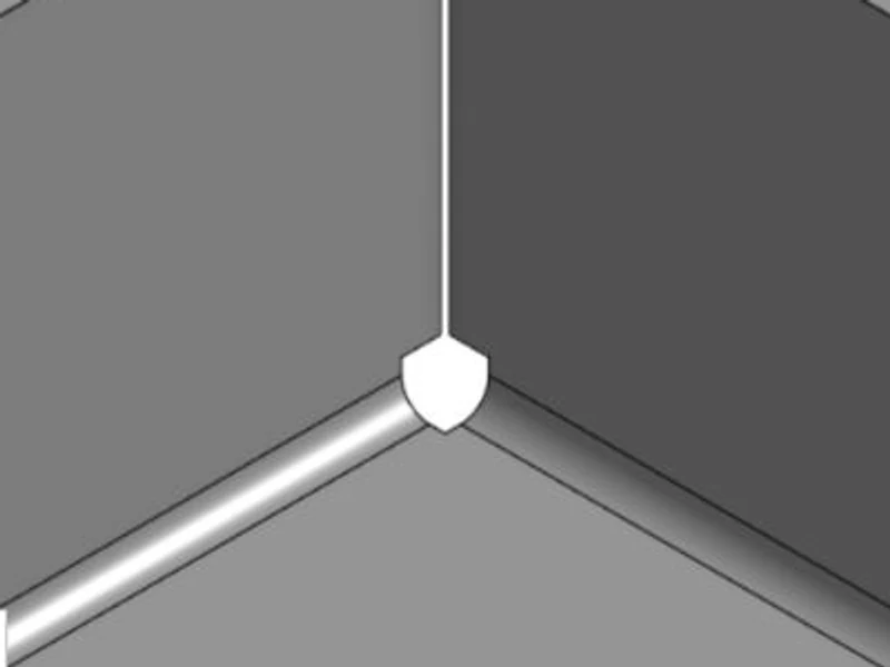
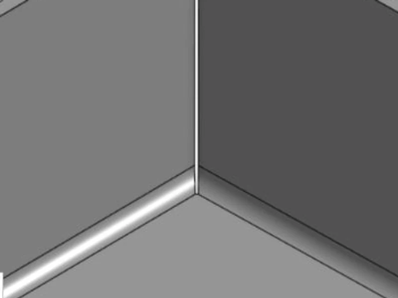
The large corner opening disappears and the bent walls meet much more closely at the base.
No cutout / Minimal gap 0.020 REF
View A / Formed cornerOnshape
View B / Flat patternTop
Good for
Worth evaluating when a small visible opening or close corner fit matters, including a planned welded enclosure. In this comparison it retains much more material at the meeting point of the bends.
Things to watch
A closed CAD corner still has a seam. It is not automatically welded, sealed, or leak-tight. Verify bend sequence, local interference, real bend radii, and weld access. The extra material near the bend intersection may make forming less forgiving.
Notes: unless otherwise specified1. Crops from actual Onshape screenshots. 2. Uses and tradeoffs are design guidance, not a forming test.
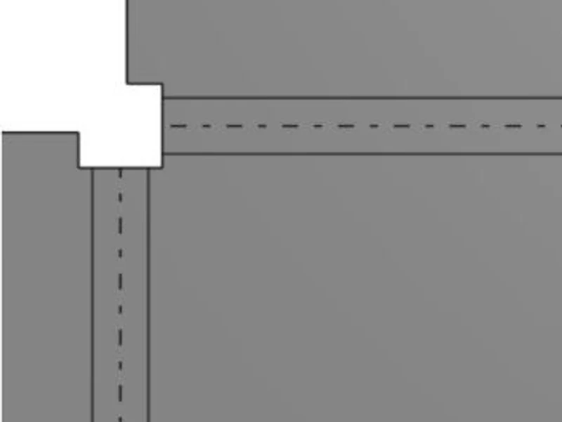
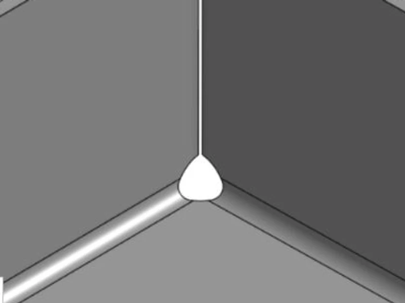
A small opening remains, with a simpler notch in the flat pattern than the enlarged reliefs.
Basic notch / Minimal gap 0.020 REF
View A / Formed cornerOnshape
View B / Flat patternTop
Good for
Useful as a baseline when a modest opening is acceptable and you want to see Onshape’s basic corner treatment. Compare it directly with Closed and the larger sized reliefs before choosing a final detail.
Things to watch
The small CAD opening does not prove that there is enough forming clearance. Check for local stretching, tearing, bulging, and wall contact on a trial bend. Do not assume Simple is the best option merely because the cutout is smaller.
Notes: unless otherwise specified1. Crops from actual Onshape screenshots. 2. Uses and tradeoffs are design guidance, not a forming test.
The table collapses the six sheets into the decisions that actually differ: how the opening is controlled, what it leaves at the corner, and what kind of part each one suits as a first pick.
Type
Control
Opening on this box
Material left at the corner
First pick for
01 Square - Sized
Width, 0.500 in
Square cutout, straight sides
Least of the sized pair; sharp internal corners
Open trays where the relief must be easy to inspect and dimension
02 Rectangle - Scaled
Scale, 1.5
Rectangle that follows the bend geometry; looks nearly square here
Varies with thickness and radius
Families of parts across several gauges from one model
03 Round - Sized
Diameter, 0.500 in
Circle, smooth boundary
Similar to the square; no re-entrant corners
Fabricated trays and anything that will be finished or fatigue-loaded
04 Round - Scaled
Scale, 1.5
Circle, larger than the sized round at these inputs
Less than 03; harder to close with a weld
Rounded relief that should adapt when the gauge changes
05 Closed
Minimal gap only
No cutout; walls meet closely at the base
The most of the six
Welded or sealed enclosures where the seam will be filled
06 Simple
Minimal gap only
Small basic notch
Nearly all; small opening remains
Baseline and quick prototypes where a modest opening is fine
Enlarging a relief trades clearance for material.These six styles are not a universal ranking. Enlarging a particular opening can increase clearance, but may reduce local stiffness and leave a larger opening to close. If the corner will be welded, that removed material is weld fill you have to put back. If it stays open, it is simply a bigger hole in the finished part.
05 / Sized vs. Scaled
A number you type, or a number you measure.
Sized options give a stated width or diameter. Scaled options respond to the bend geometry. The difference is not cosmetic; it changes who is responsible for the final opening.
Sized / 01 and 03
W 0.500 · ø 0.500
The opening is the number you typed
Dimension it on the drawing exactly as entered. Inspection can check it with a caliper or pin.
It does not move when thickness or bend radius changes, which also means it does not protect you when they do.
Square - Sized at 0.250 in triggered a relief-too-small warning on this box; 0.500 in regenerated. That is Onshape’s geometry check, not a forming limit.
Scaled / 02 and 04
Scale 1.5
The opening is a result
1.5 is a dimensionless multiplier applied to the local bend geometry. It is not 1.5 inches, and the same 1.5 on a rectangle and a round does not give equal area or width.
Change thickness or radius and the relief follows. Good for a model that serves several gauges; risky if nobody re-measures.
Measure the resulting opening in the flat pattern and put that number on the drawing.
On this symmetric box the scaled rectangle can look nearly square in the folded view, and the scaled round is clearly larger than the fixed 0.500 in round. Neither of those observations is visible from the setting alone. Both come from looking at View B.
06 / Closed vs. Simple
Two rips, one field that matters.
Closed and Simple retain more material than the enlarged openings in this comparison. Minimal gap controls the rip clearance, but the resulting corner still needs its own geometry and forming checks. Simple leaves a small basic notch in this model.
Closed pulls the walls together at the base and keeps the most material at the meeting point of the bends. That is what makes it worth evaluating for a welded enclosure, and also what makes forming less forgiving: there is more metal in the bend intersection and less room for it to move. Simple leaves a small basic notch. It is Onshape’s default treatment and a fair baseline, but the small opening in CAD does not prove there is enough forming clearance.
A closed corner in CAD is still a seam.It is not welded, sealed, or leak-tight until someone welds and seals it. If the part needs a closed interior, model the relief, form the box, then weld. Call the weld out on the drawing so the seam is finished on purpose and not treated as a forming defect.
Minimal gap controls rip clearance; it does not establish corner-opening size or prove forming clearance. Set it for the intended seam, then inspect the actual corner. See the separate Onshape controls.
07 / Before You Cut or Bend
Choose the opening and the process together.
Six checks that turn a comparison model into a part. Each one is cheap in CAD and expensive on the brake.
01
Start with the real bend data.
Confirm the 5052 temper and rolling direction, then use the shop’s inside radius and bend allowance or K factor. A material-library assignment does not automatically calibrate the sheet-metal bend settings.
02
Plan the seam and finish.
Decide whether the box is open-seamed, welded, or sealed. Closed relief does not make it leak-tight. Allow for practical seam fit, weld access, distortion, cleanup, and any coating.
03
Inspect the whole flat pattern.
Check all four corners, slot widths, residual narrow tabs, cut-edge quality, and nearby holes. Enlarging a relief may improve clearance but removes material. Deburr the cut edges before forming.
04
Use size and scale deliberately.
Sized options give a stated width or diameter. Scaled options respond to the bend geometry. Equal scale numbers do not mean equal cutout area. Measure the resulting opening when documenting the part.
05
Check how the box will be formed.
Verify tooling clearance and the sequence for all four walls. A model that unfolds successfully is not a press-brake collision or material-deformation simulation. Make a trial part when the fit matters.
06
Adjust the examples in Onshape, not in your head.
Open a numbered Part Studio and edit Sheet metal model 1 › Relief. That controls all four corners together. Use the separate Corner feature for an individual corner override.
08 / Configure for Xeon
Use the catalog bend data. Establish the corner dimensions.
The demonstration used radius 0.125″, K-factor 0.40 and gap 0.020″ to compare CAD appearances. The current 0.125″ 5052-H32 material page lists radius 0.189″ and K-factor 0.44 for W30 tooling.
Correction: the former 0.018″ bend-line estimate is not a validated Minimal gap or Corner relief width. The demo’s 0.500″ sized opening regenerated in CAD; that does not establish a forming minimum either.
Choose the seam clearance separately from the relief-opening size. Check the flat pattern, both bend regions, actual cut widths and forming sequence. For a welded corner, agree the root gap and joint preparation with the welder.
09 / Edit the Examples
Open a sheet, change one field, watch the corner.
The six Part Studios are editable. The fastest way to understand a relief type is to open its tab, change one setting, and look at the flat pattern again.
01
Open a numbered Part Studio.
Each sheet above links to its tab in the corner relief examples document. Tabs 01 through 06 are the six types; the Assembly tab is not part of the comparison.
02
Edit Sheet metal model 1 and open the Relief group.
Corner relief type is the dropdown with the six options. Below it, sized types expose a width or diameter, scaled types expose a scale, and Minimal gap sits with them. This one feature controls all four corners together.
03
Override a single corner with the Corner feature.
If one corner needs a different treatment, do not change the model-level setting. Add a Corner feature and pick that corner. The other three keep the model default.
04
Read the flat pattern, then measure it.
Open the flat view. Measure from each bend line to the edge of the adjacent flange, and measure the opening itself. Those are the numbers that belong on the drawing, and the ones we check when we unfold your STEP.
Research / What Is Established
Evidence exists. A universal thickness cutoff does not follow.
More and Sapkal (2024) compared closed, open and relieved open corners in 2.5 mm mild steel using V-bending. Their reported inspections found cracks in the closed sample and no cracks in the relieved open sample. Their mounting-pan analysis also found a structural tradeoff: the open designs exceeded yield under the analyzed loading. This is evidence that forming success and structural performance are separate checks—not a ranking of Onshape’s six styles across alloys or thicknesses. Read the paper’s abstract and methodology.
Ibrahim’s 2025 thesis studies corner hemming by incremental sheet forming in 1.0 mm DC04 steel. Relief geometry, flange length and corner radius affected the outcome. This is adjacent evidence; its process and material differ from a press-brake 5052 box. Read the thesis.
SSAB’s bending guidance identifies material properties, thickness and tooling among the variables governing bend behavior. It does not establish corner-relief-style cutoffs. In the sources reviewed, we did not find a transferable table saying a particular Onshape relief stops working above a specified thickness for every Xeon alloy.
Current recommendation status: proposed starting configurations.Round - Sized is our candidate for a general open corner. Closed is a candidate for reducing a weld opening only after successful trial forming and agreement on joint fit. Neither is a universal best choice or a production-verified material rule.
Proposed Xeon corner-relief study
This program is proposed, not completed. Start with 5052-H32, A1008 and 304, choosing three stocked, supported thicknesses per material. Compare all six CAD styles with three independently cut and formed specimens per condition: 162 corner specimens for an initial screening at one defined setting per style.
Control the comparison.Record actual thickness, material lot and temper, grain orientation, laser settings, edge preparation, die, punch, radius, bend angle, bend order and machine setup. Block by material/thickness and randomize specimen order within each block.
Measure geometry, not just CAD labels.Record opening width/thickness, depth/thickness, radius/thickness, removed area, smallest ligament and seam gap. For sized/scaled comparisons, include matched opening dimensions or area where possible; Closed and Simple are different constructions.
Find the operating window.After screening, vary opening size and radius/tooling within supported limits. Test both grain orientations and the actual box bend sequence. A four-corner box is not four independent material replicates.
Score forming and welding separately.Inspect cracks after each bend, distortion, thinning, seam gap and angle error. Use a defined inspection method and acceptance criteria. For the welding subset, hold the welding procedure, filler, fixtures and target root gap constant; record fit-up time, filler use, weld time, distortion and leak results where sealing is required.
Confirm before publishing a limit.Three specimens are screening evidence, not a reliability guarantee. Repeat promising boundary conditions across additional lots and operators, and assess service loads separately. Publish only the tested material, thickness, tooling and geometry range with sample count, failures and uncertainty.
The useful result would be a tested operating range and a preferred option for each application—not a single thickness threshold detached from radius, opening size and forming method.
10 / Release Checklist
Six lines before you upload.
Each one maps to a sheet or a section above, and each one prevents a corner from being discovered on the brake.
Upload the formed STEP with the corner already decided.
Pick the material and thickness when you upload. We unfold against the die that will run the job, and a corner that already clears the published gap forms the first time.