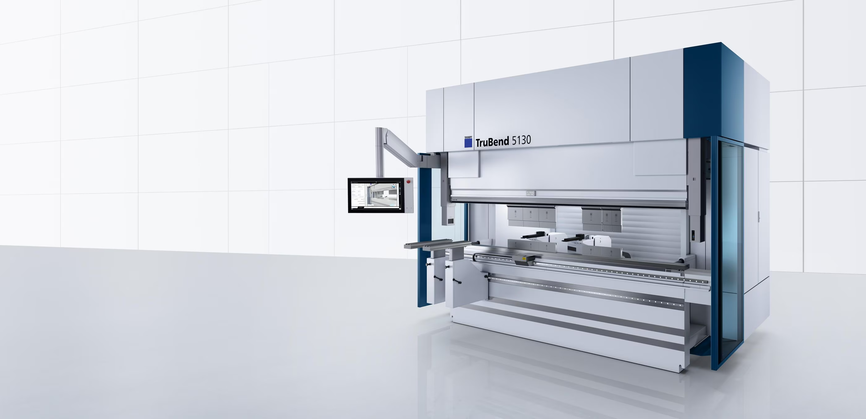
What bend radius should you use?
Use a radius your fabricator can form in the specified material and thickness. The sheet metal bend radius in your CAD model should reflect that reviewed setup, while meeting the part’s fit and strength requirements.
For a starting point, jump to the sheet metal bend radius chart or look up a material and thickness. The values below are Xeon NC planning references. They are not universal minimums or measured results for your part.
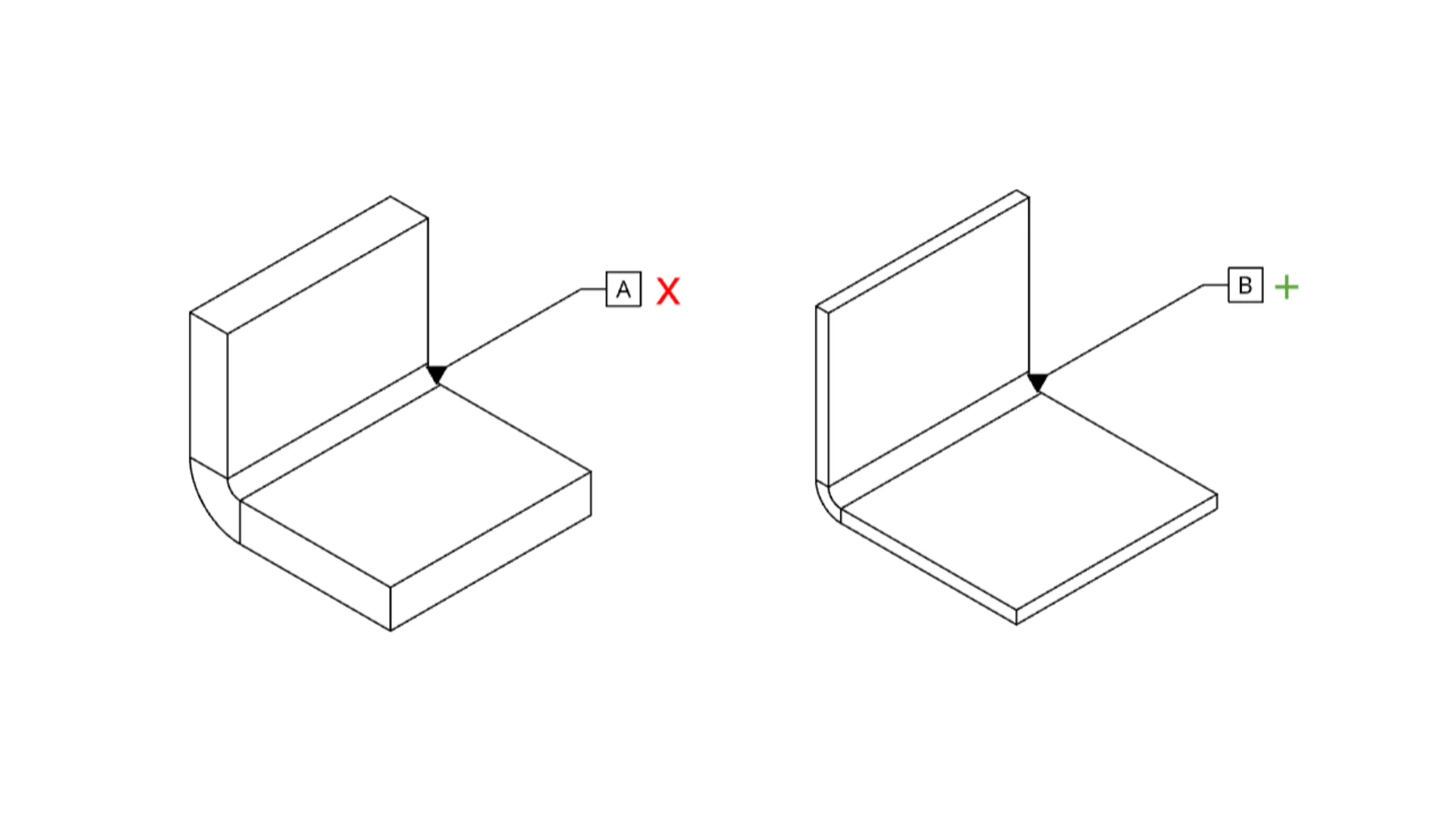
Ri describes the inside curve. The outside radius is Ri + T for an ideal bend with constant thickness.
The minimum depends on alloy, temper, thickness, grain direction, and forming conditions. Confirm it using the material supplier’s guidance.
The die and material lookup provides a starting value for CAD and process review.
A finished radius has variation. Specify a radius tolerance when it affects function, and agree how it will be checked.
How the V-die affects the inside radius.
In air bending, the punch loads the sheet between the two die shoulders. The sheet does not fully seat against the bottom of the V.
The die opening influences the natural radius, but it does not determine the result by itself. Material properties, thickness, bend angle, and punch geometry also matter. WILA describes these relationships in its V-opening guide.
The approximation Ri ≈ 0.16 × V is useful for understanding the reference values below. Treat it as a planning estimate, not a formula that guarantees the same radius in aluminum, mild steel, and stainless steel.
Sheet metal bend radius chart.
These five inside-radius values are stored in Xeon NC’s bend-reference data. Select the material and thickness in the lookup below to find its assigned reference.
| V-opening (mm / in) | Inside radius (in) | Inside radius (mm) |
|---|---|---|
| 8 / .315 | .050 | 1.270 |
| 12 / .472 | .076 | 1.930 |
| 20 / .787 | .126 | 3.200 |
| 30 / 1.181 | .189 | 4.801 |
| 50 / 1.969 | .315 | 8.001 |
Millimeter radii are converted from the stored inch values using 25.4 mm per inch and rounded to three decimals. Tool assignment, minimum flange, and permissible radius require review for the actual material, bend angle, and part geometry.
Example: a 0.060-inch cold-rolled steel part
The lookup pairs this thickness with W12 and a 0.076-inch inside radius (about 1.93 mm). That gives Ri/T = 0.076/0.060 ≈ 1.27T. For ideal constant-thickness geometry, the outside radius is 0.076 + 0.060 = 0.136 inch. This is a CAD planning example, not a minimum-radius qualification.
Why the 1T rule does not fit every thickness
A single die reference covers several thicknesses, so the reference Ri/T ratio changes. Compare these examples before choosing a default radius in CAD.
Use these ratios to check your assumptions. They do not establish crack resistance, dimensional tolerance, or a safe minimum for another alloy or temper.
Look up a radius by material and thickness.
Choose the material and thickness to see its stored planning values. Confirm the radius and tooling before releasing the part; this lookup is not a forming simulation or inspection result.
The flange and Ri + 2T values are screening references only. They do not replace the die manufacturer’s minimum-leg data or a check of support under a nearby hole. Use the hole-to-bend distance guide and bending distortion examples when an opening is close to a bend.
Material limits are separate from the chart.
A tooling reference tells you what is planned. It does not prove the material can accept that bend.
Check the exact alloy, temper, thickness, and bend orientation. Tensile-test elongation alone is not a pass/fail test for a bend; supplier bend data and forming trials are more useful for a critical application.
| Material | What to verify | Design action |
|---|---|---|
| 5052-H32 aluminum | Thickness, temper, and bend orientation in the supplier’s recommendations. | Compare the proposed radius with the applicable material guidance; do not reuse one minimum across all thicknesses. |
| 6061-T6 aluminum | Product form, thickness, condition, and the supplier’s recommended bend radius. | Review the setup rather than copying a 5052-H32 bend. See the 5052 vs 6061 comparison. |
| Carbon steel or stainless steel | The full grade and condition, thickness, cut-edge condition, and required bend angle. | Match the proposed process to the actual stock specification and functional requirements. |
The Atlas 5052 datasheet and Kaiser 6061 datasheet illustrate why alloy and thickness need separate treatment. Use the current recommendations for the stock you actually purchase.
Check rolling direction
Bendability can change with the bend line’s orientation to the sheet’s rolling direction. Identify both directions on the drawing when they matter. A multi-sided enclosure may have bends in different orientations, so review each bend instead of applying a universal grain-direction multiplier.
Six checks before releasing the model.
Connect the CAD geometry to the material, process, and inspection requirements.
Need to protect a nearby hole? Read how close a hole can be to a bend and the illustrated hole pull-through and bending distortion guide.
What changes when you change the radius?
| Check | Why it matters | Next step |
|---|---|---|
| Flat pattern | Radius affects bend allowance and deduction. The change in total blank length depends on the dimensioning convention and which dimensions stay fixed. | Recalculate using the reviewed radius and K-factor; compare the required finished dimensions. |
| Springback | Elastic recovery varies with material properties and geometry, including Ri/T. | Confirm the angle-control method and the required finished tolerance. |
| Holes and cutouts | Different tooling can change which areas are supported during forming. | Review nearby openings against the actual die and bend location. |
| Flange length | A short flange may not remain supported on the selected die shoulders. | Check the manufacturer’s minimum leg for that tool and angle, using its stated measurement convention. |
| Forming force | Changing die opening changes the force required for an otherwise comparable air bend. | Check both machine and tooling capacity for the material and bend length. |
For the calculations, use the bend allowance and bend deduction calculator. For angle measurement, see ACB optical angle measurement. Both support process planning; neither makes a critical radius tolerance unnecessary.
When the reference radius does not fit.
Explain which feature needs a tighter or larger radius and why. A mating part, seal, cosmetic surface, or strength requirement may justify another process.
Depending on the part, options can include different tooling, bump forming, roll bending, or a designed relief. Each changes the manufacturing and inspection requirements. Confirm availability and feasibility with Xeon NC before specifying the process.
Use the tooling selection guide, press-brake tooling library, and bend-affected zone guide to prepare the review.
Sheet metal bend radius questions.
How do I use a sheet metal bend radius chart?
Start with the material, temper, thickness, and bend angle. Find a tooling reference, then confirm that the planned inside radius meets the material supplier’s bend guidance. Xeon NC’s chart lists planning values in inches and millimeters; the material lookup narrows the reference by thickness. Confirm the setup before releasing a critical radius.
Is the minimum bend radius the same as the inside bend radius?
No. The inside radius describes the curved inner surface of the formed part. The minimum bend radius is a material and process limit under specified conditions. A tooling reference is a planning value. A measured production radius can differ from that reference.
Should the sheet metal bend radius equal the thickness?
Not automatically. A 1T radius means the inside radius equals sheet thickness. In the Xeon reference data, 0.060-inch cold-rolled steel is paired with a 0.076-inch radius, or about 1.27T. Use the reviewed material and tooling combination instead of assuming every bend should be 1T.
Can I use 0.16 times the V-die opening for every material?
No. It is a planning approximation, not a universal material law. Material strength, thickness, bend angle, and punch and die geometry influence the formed radius. The chart preserves Xeon’s reference values; it does not guarantee the same result for every alloy or setup.
What is the minimum bend radius for aluminum?
There is no single minimum for all aluminum. Check the supplier’s recommendations for the exact alloy, temper, thickness, and rolling direction. A radius used for 5052-H32 should not be carried over to 6061-T6 without review. For a functionally critical bend, agree on the process and inspection requirement with the fabricator.
Will a larger bend radius prevent hole distortion?
Not necessarily. A larger radius or wider die changes the bend geometry and the area that must remain supported. A nearby hole or cutout can still distort. Check its edge against the bend location and actual die-support area; do not rely on radius alone.
Eight checks before you upload.
Use this checklist to prepare a manufacturing review. Checking every box does not replace process approval.
Get your bent part reviewed.
Send your formed STEP file, material, thickness, and critical dimensions. Include the drawing when a radius or fit needs a specific tolerance.
Get a bending quote →