Now accepting custom orders — Get your instant quote →
Skip to hardware insertion overview
PEM self-clinching hardwareXeon NC · Installed in-house

Hardware
insertion.

Threads, mounting points, and precise spacing. We press the hardware into your sheet metal so your parts arrive ready for assembly.

Isometric line drawing of Xeon NC’s Auto-Sert AS-7.5 hardware insertion press
01 / Isometric viewAuto-Sert AS-7.5
Inside the process

Controlled force.
Permanent fit.

Our Auto-Sert AS-7.5 seats self-clinching hardware with a controlled hydraulic press load.

Meet the machine
Press capacity
7.5 US tons
Ram stroke
6 in
Hardware families
5
Thread systems
Inch + metric
Installation
In-house

Auto-Sert AS-7.5.
Built for the clinch.

A hydraulic insertion press for self-clinching nuts, studs, and standoffs in flat or formed sheet metal. The tooling and installation force are selected for the fastener and the part.

Machine study / AS-7.5Front + side elevation
Front and side line drawings of the Auto-Sert AS-7.5 hardware insertion press
02 / Front view03 / Side view
Maximum press force
15,000 lbf
Ram stroke
6 in / 152 mm
Hydraulic pressure
40–3,000 psi
Oil reservoir
12 US gal

Published AS-7.5 machine ratings from Auto-Sert. Installation force depends on the selected hardware, material, and tooling.

03 / The processPrepare your drawing

Pressed in.
Ready to build.

The fastener’s clinching feature captures displaced sheet metal, creating a permanent mechanical connection.

01

Prepare the hole

Cut the mounting hole to the selected fastener’s specified diameter and tolerance.

02

Locate the hardware

Position the fastener on the specified side and support the part with the correct anvil.

03

Apply the press load

Use a controlled squeezing force to form the sheet metal into the fastener’s clinching feature.

04

Check the installation

Inspect seating, orientation, and hardware count before the next manufacturing step.

04 / Hardware typesBrowse the PEM catalog

Five families.
One finished part.

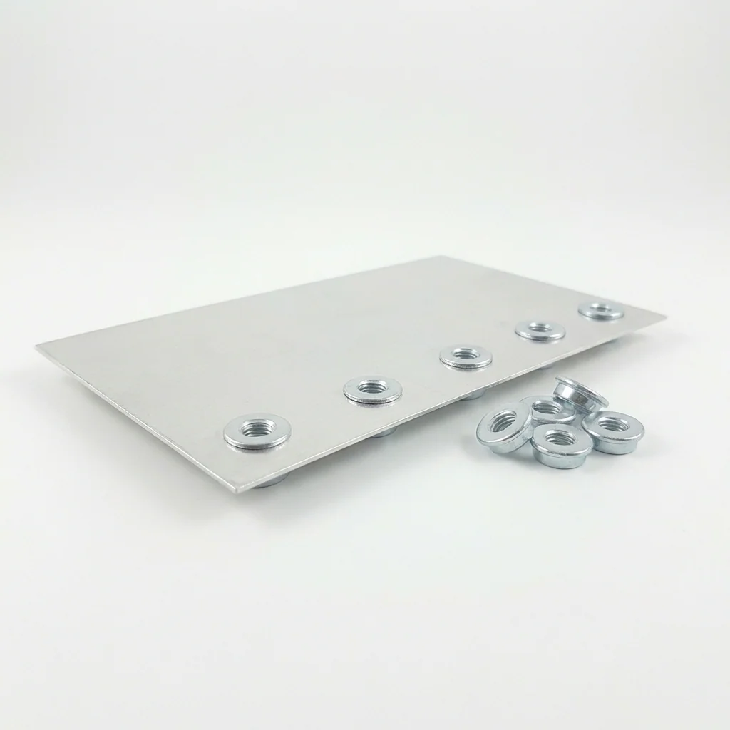
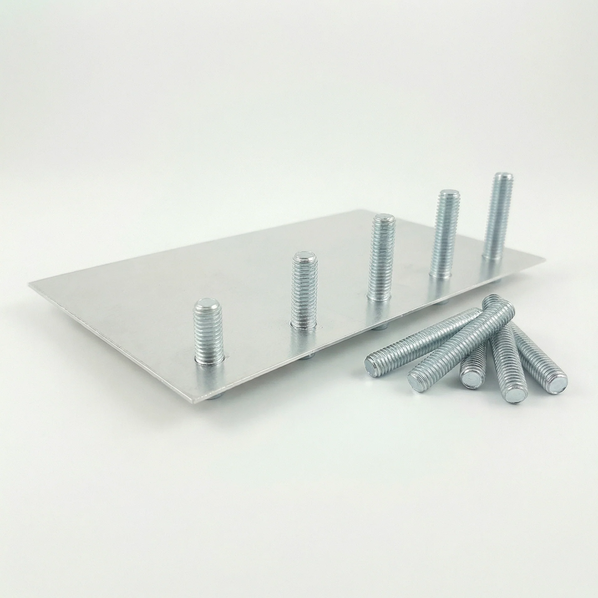
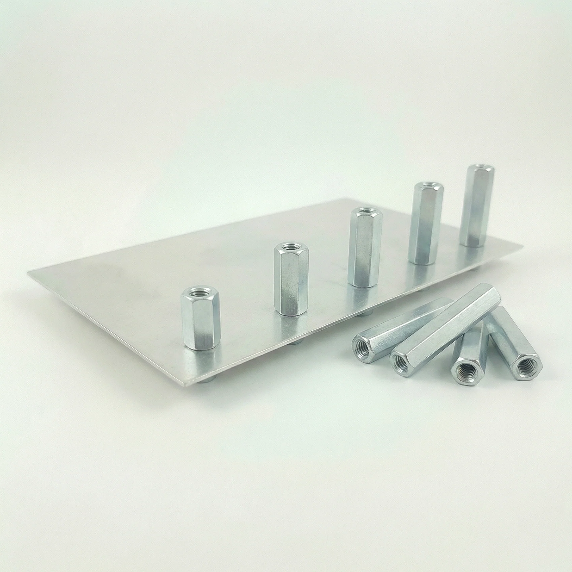
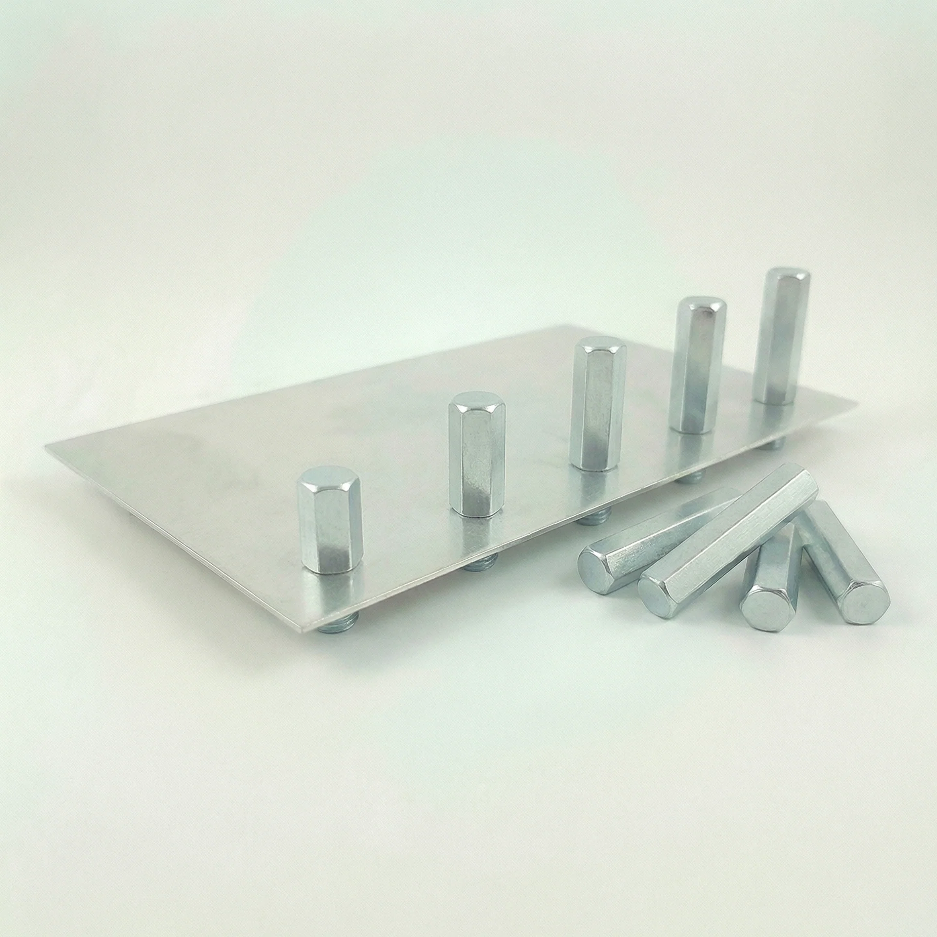
Combine nuts, studs, and standoffs on the same part. Call out the exact hardware and installation side in your drawing.
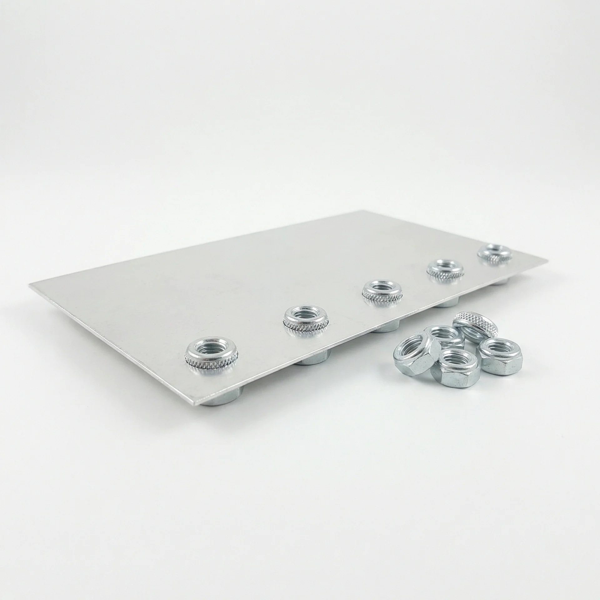
Start with your material

Which hardware
fits your sheet?

Use the hardware size chart to compare fasteners against your alloy and thickness.

Open size chart
05 / Material compatibilityCheck hardware fit

Match the fastener.
To the sheet.

Fastener series, sheet hardness, and thickness determine whether a clinch will hold. Material and finish also need to suit the assembly’s environment.
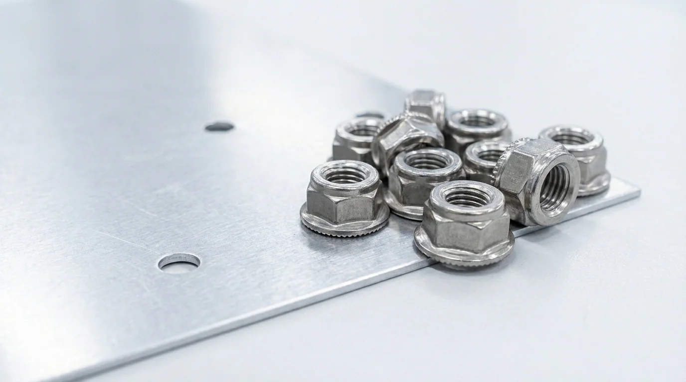
Aluminum sheet
Select a fastener rated for the alloy, temper, and thickness. Coordinate the installation sequence with any anodizing requirements.
Steel sheet
Check the fastener’s sheet-hardness limit, shank length, and specified mounting hole.
Stainless sheet
Use a fastener series specifically rated for installation in stainless sheet; ordinary stainless hardware is not automatically suitable.
Selection of self-clinching sheet metal hardware
Fastener series · Sheet thickness · Material hardness
06 / Service specificationsFull hardware size chart

The details.
Before assembly.

Start with your hardware part number. Hole dimensions, minimum sheet thickness, and edge distances follow the selected fastener’s data sheet.

Hardware types
PEM nuts · Flush nuts · Threaded studs · Through standoffs · Blind standoffs
Inch threads
#4-40 · #6-32 · #8-32 · #10-32 · ¼-20 — availability varies by family
Metric threads
M2.5 · M3 · M4 · M5 · M6 — availability varies by family
Sheet materials
Aluminum 5052 / 6061 · Steel A1008 / A36 · Stainless 304 / 316, subject to fastener and sheet-hardness compatibility
Hole size & thickness
Use the exact hole diameter, tolerance, and minimum sheet thickness for the chosen part number. Check the hardware size chart.
Installation sequence
Planned around tooling access, bending, and finishing. Include coating and anodizing requirements with your drawing.
File requirements
DXF or STEP plus a drawing or hardware schedule identifying part numbers, quantities, and installation sides.
Production timing
Hardware selection and availability are reviewed with the part quote.

Call it out.
Make assembly simple.

A clear hardware schedule helps us install the right fastener, in the right location, from the right side.

01 / Specify the complete part number
Include the series, thread, shank code, and length where applicable, plus quantity.
02 / Show the installation side
Mark each hardware location and the side from which it is installed. Allow room for the fastener and mating assembly.
03 / Use the specified mounting hole
Follow the fastener data sheet. Avoid countersinking or deburring the mounting hole unless its installation instructions require it.
04 / Leave access for the tooling
Check edge distance and distance to bends against the selected fastener’s requirements. Include formed views where access is tight.
05 / Identify the finish
Tell us about anodizing, powder coating, and thread masking so the installation sequence can be planned correctly.
06 / Confirm sheet compatibility
Use the specified thickness and hardness range for the fastener. Check stainless-sheet applications against the appropriate series.

Installation reference: PEM self-clinching fastener handbook.

Your next assembly starts here

Hardware installed.
Assembly ready.

Upload your part file and include the hardware callouts. We’ll review the fit and install your fasteners in-house.

Quote your parts