01 / Understand the mechanism
Why do holes distort during press brake bending?
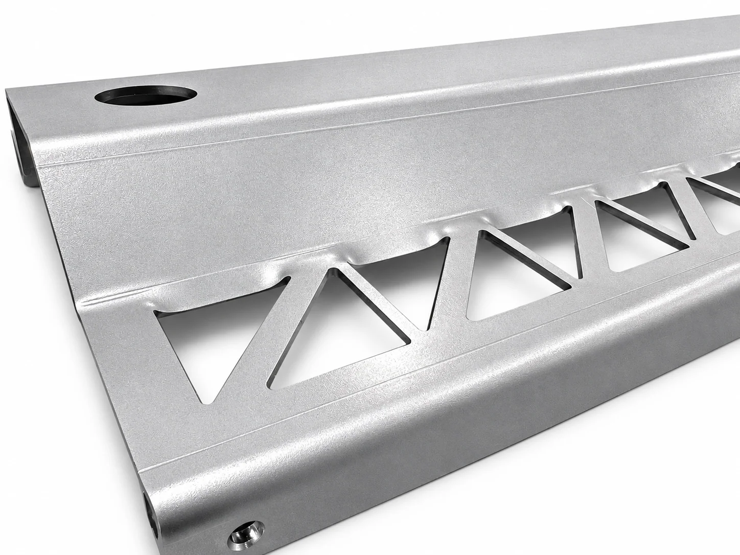
In conventional V-die bending, the punch pushes the sheet between two die shoulders. A hole or cutout can put a free edge inside that unsupported span. The surrounding material forms while the edge tends to remain flatter, producing local deformation. Mate’s tooling guidance describes this behavior for both cutouts and tapered edges. See the tooling explanation.
Here, hole pull-through means the distortion of a hole and its surrounding material during bending: the edge may draw toward the bend, flare, or lose its intended profile. It is a forming problem, distinct from a bolt or screw pulling through a sheet under load.
The whole part may still reach its programmed angle. An unsupported region may fail to follow the intended radius while adjacent strips bend. The resulting mismatch is the distortion you see.
CNC positioning does not remove the need for die contact. Unsupported sections can still affect the angle and the position of the bend. Check the profile along its length, rather than judging the part from one angle measurement. SendCutSend also identifies incomplete bend support as a design issue.
02 / Read the shape
Hole pull-through and cutout distortion: visual examples.
These six illustrations explain the geometry. They are not dimensioned inspection records; material grade, thickness, tooling, and acceptable distortion must be specified for the actual part.
A hole beside the bend
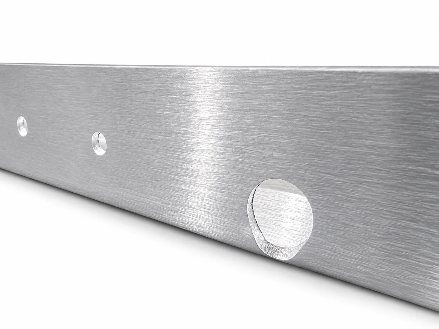
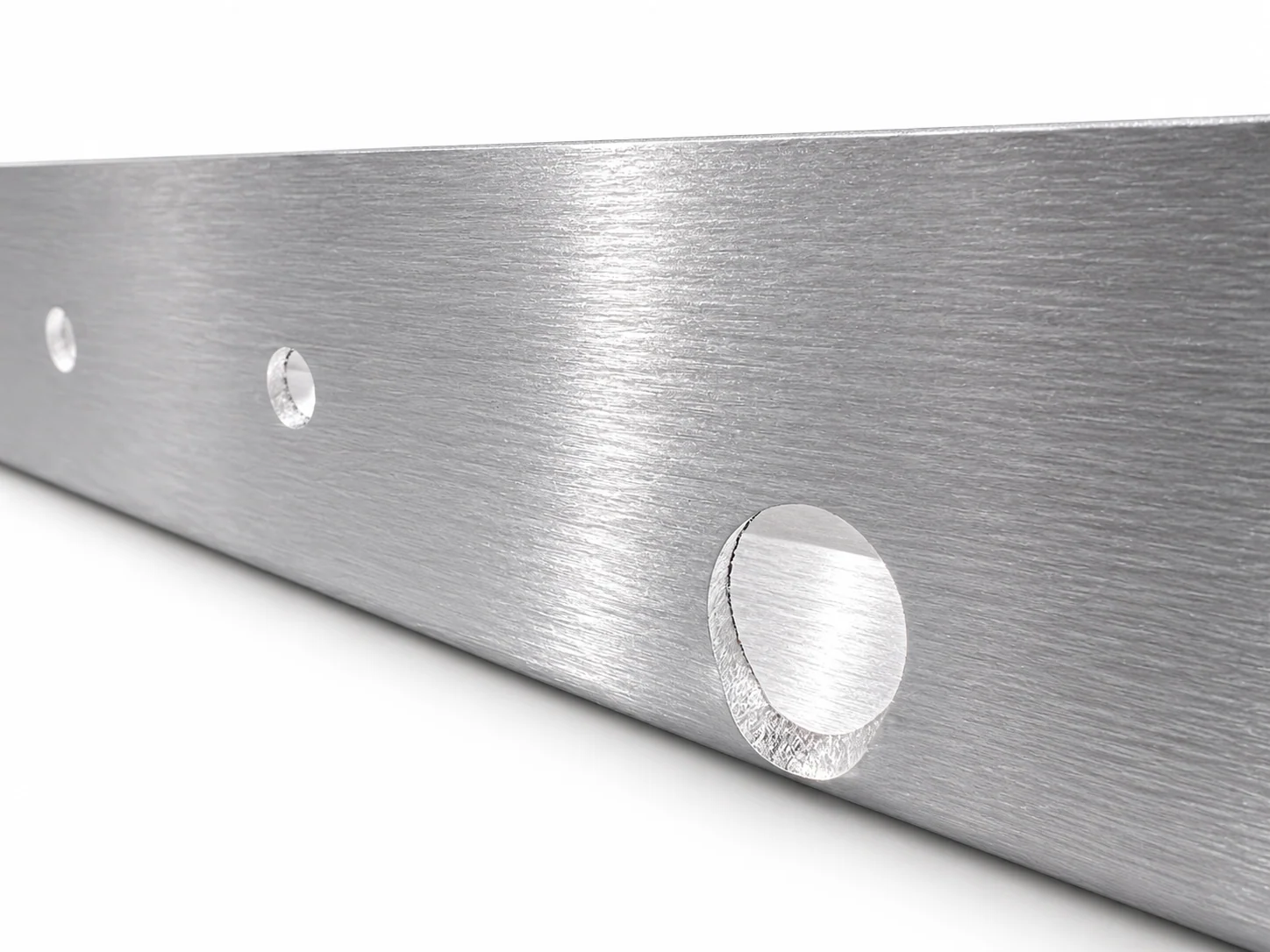
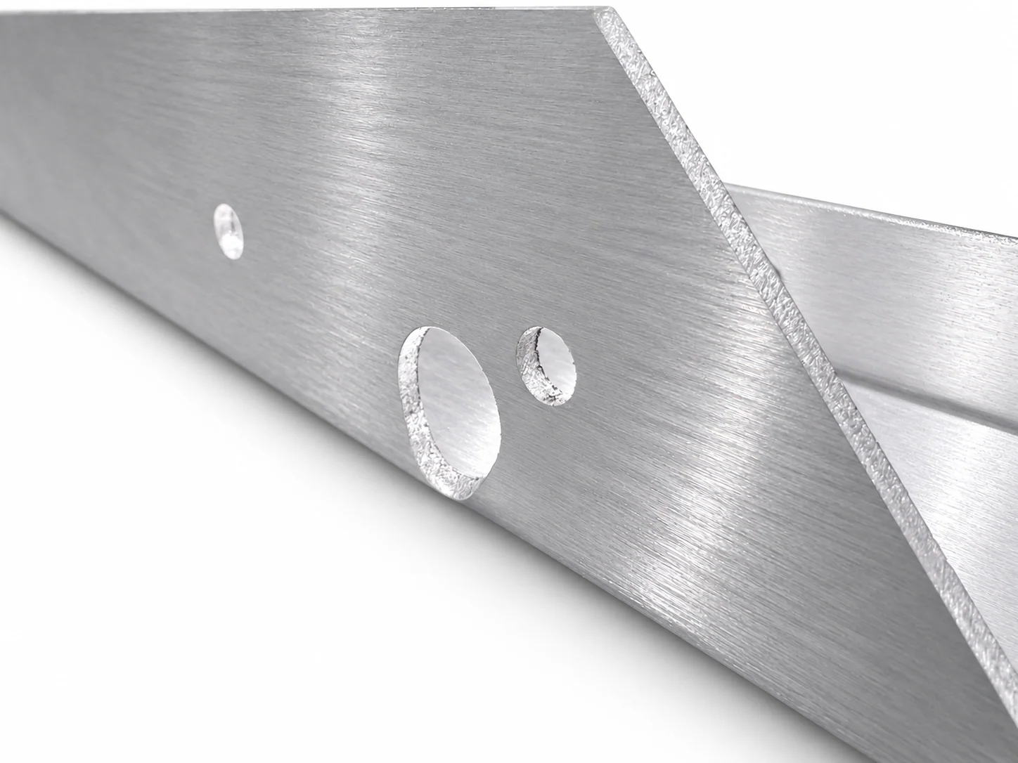
For a mounting hole, ask what must still work after forming. Does a fastener need to pass through? Must a washer sit flat? Does the hole locate the assembly? Call out the finished hole position and function in the drawing so a visually small change does not become an assembly problem.
Repeated cutouts beside a bend
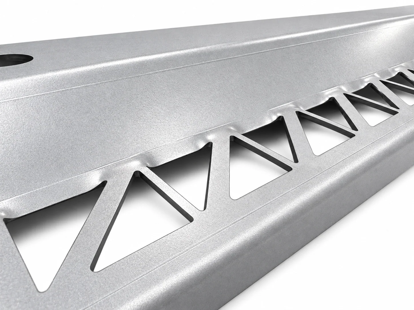
Review the nearest edge of every opening, not just the hole centers. On a vented panel, the useful question is whether the tooling can form the remaining material consistently across the pattern. A long, uninterrupted flange at one end does not tell you what happens beside the next cutout.
03 / Check the whole flange
Unsupported flanges can form unevenly.
A flange must retain enough contact with the lower die throughout forming. A short leg or a tapered end may lose that support. AMADA explains minimum flange size in terms of keeping the material on the die shoulders through the completed bend. AMADA bending fundamentals, section 7-10.
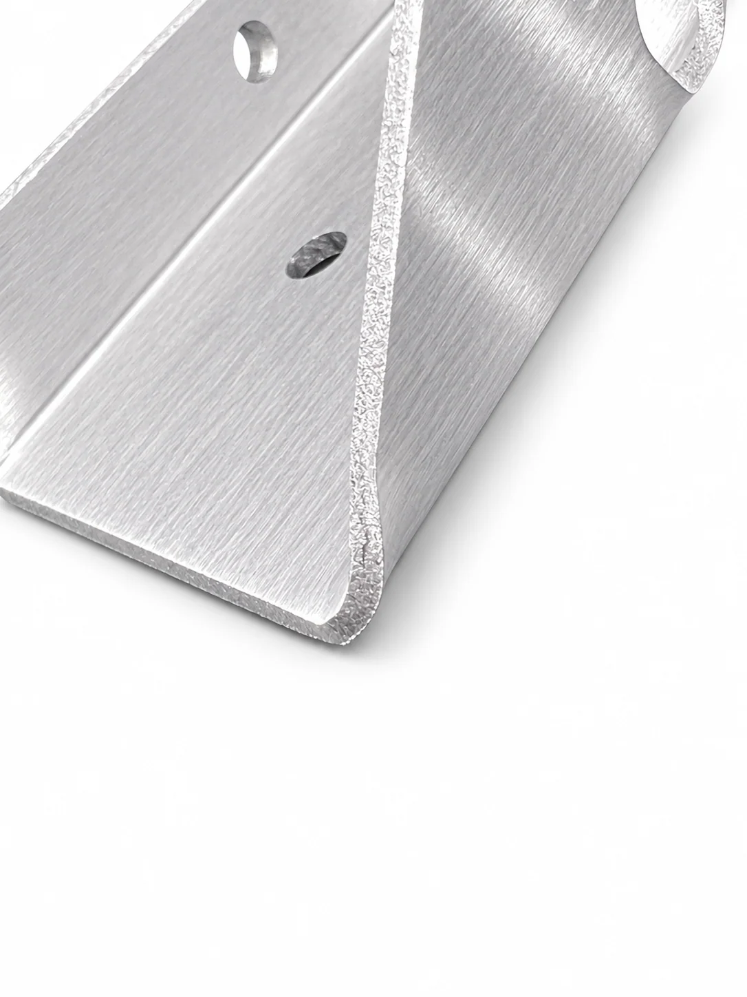
For an irregular part, review the narrowest local flange section as well as the overall flange length. Label the bend direction and include the folded model. That lets the fabricator evaluate where the sheet contacts the tools during the stroke.
Use Xeon’s minimum leg length calculator to explore the tooling geometry, then confirm the production setup with the selected material and thickness.
04 / Dimension the right feature
How far should a hole or cutout be from a bend?
Use the clearance required for the actual material and tooling. Do not transfer a number from one process or thickness to another. The die opening, tool geometry, bend angle, and feature shape all matter to the review.
| Check | What to identify | Why it matters |
|---|---|---|
| Hole-to-bend distance | Nearest hole edge and the stated bend reference. | A hole-center dimension alone hides the remaining material. |
| Cutout clearance | Closest boundary, including slot ends and angled corners. | The nearest point can differ from the nominal center of the feature. |
| Minimum flange length | Shortest local leg and the selected die’s requirement. | The outside envelope does not describe every section of an irregular flange. |
The flat-pattern bend centerline, inside bend tangent, and outside face are different references. A clearance value is useful only when the drawing and the fabrication rule use the same reference.
For the detailed placement workflow, use our hole-to-bend distance guide. For a wider view of the forming region, see the bend-affected zone guide.
05 / Choose a design change
How to reduce bending distortion.
Move the opening away from the bend.
Where the assembly allows it, increase clearance before adding complexity. Check the mating part and edge distance at the same time.
Review a longer or more continuous flange.
Bring the narrow or tapered section into the tooling review. Ask whether changing that section can provide the required contact.
Consider making the critical hole after bending.
AMADA lists post-bend hole making as one option. Confirm tool access, fixturing, the finished datum, and the additional operation before choosing it.
Use a relief only with a defined purpose.
A slit between a hole and a bend can change local deformation. Its shape also changes the part’s remaining section. Review the joint’s load requirements and read the hole pull-through and bend-relief guide before adopting that approach.
Ask about a different forming tool.
Some tooling uses moving support surfaces to reduce distortion near features. TRUMPF describes its RollBend tool as distributing pressure through supporting side plates. Availability and suitability must be confirmed for your job. TRUMPF bending tool reference.
The first, third, and fourth options follow the spacing, post-bend machining, and slit approaches in AMADA’s hole-deformation guidance. No single option is a universal fix. Review a representative part when the opening or flange is critical to fit.
06 / See a forming example
Watch the related hole pull-through video.
07 / Before you order
Give the fabricator the finished-part requirements.
- Material grade, temper where applicable, and thickness.
- Folded STEP model and a drawing showing bend direction, inside radius, and angle.
- Critical hole sizes and locations after forming, referenced to clear datums.
- The shortest flange sections and any cutouts beside the bend.
- Fastener, washer, sealing, appearance, or mating-surface requirements.
- Approval of any proposed relief, relocated hole, or added machining operation.
Bring us the geometry.
Have a hole or cutout close to a bend?
Send Xeon NC your model and drawing for a fabrication review. Tell us which features must stay flat, round, or accurately positioned after forming.
08 / Common questions
Press brake distortion questions.
What is hole pull-through in sheet metal bending?
In this guide, hole pull-through is local distortion around a hole during forming. The edge may flare, draw toward the bend, or lose its intended profile. The term here describes a bending problem, not a fastener pulling through the sheet under load.
Can a CNC press brake bend a part with unsupported cutouts?
The part may form, but local edges can distort even when the overall bend angle is correct. Review each opening against the selected tooling and the finished-part requirements. CNC positioning alone does not replace physical support from the tools.
Is there one minimum hole-to-bend distance for every part?
No. Use the requirements for the material, thickness, bend geometry, and tooling. State whether the distance is measured from the nearest cut edge to a flat-pattern bend centerline, a bend tangent, or another specified reference.
Will adding a bend relief always prevent distortion?
No. A relief can change how a region deforms, but it also changes the remaining material and must suit the part’s function. Moving the feature, using a different forming setup, or making the hole after bending may be better choices.
Technical references.
This guide combines tooling references with an illustrated design review. Tool-specific limits remain subject to the actual setup.