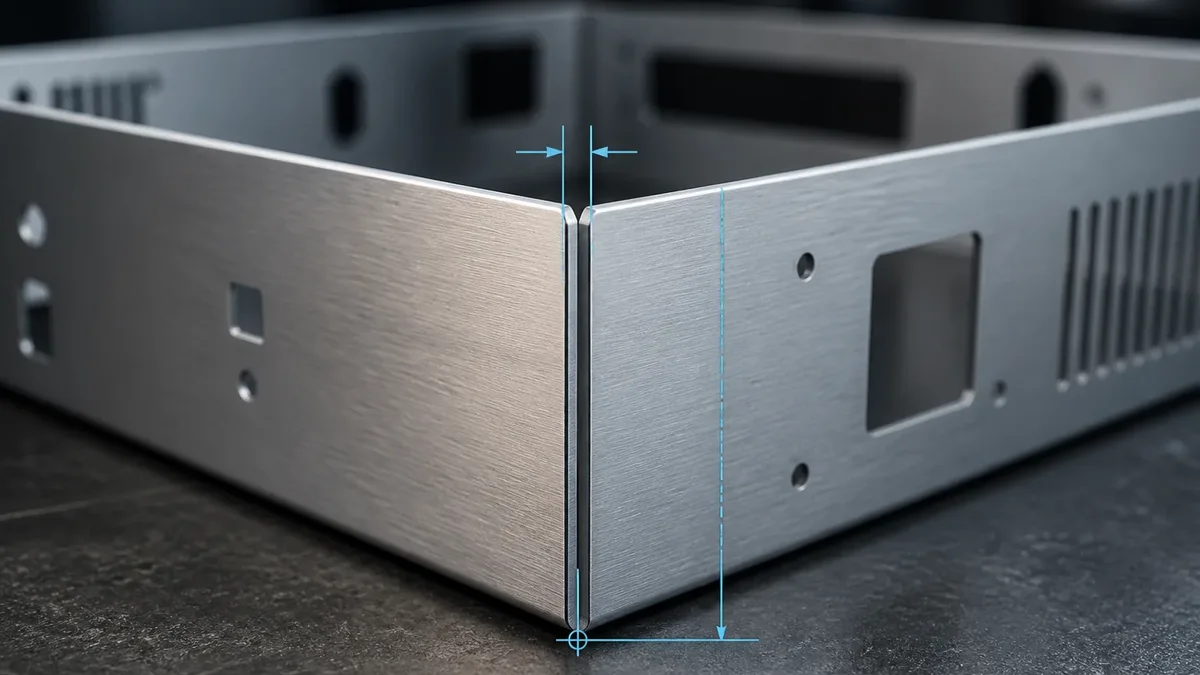
Check the corner geometry and the forming sequence.
A seam gap, a corner-relief opening and a distance measured from a bend line are different dimensions. None can be substituted for another without checking the actual geometry.
Use the selected material and thickness to get the applicable tooling and bend data. Then choose an open or welded corner, inspect both bend regions in the flat pattern, and check the walls throughout the bend sequence.
Find the value. Enter it in the matching field.
On Xeon Materials → your alloy → thickness → Bending → CORNER RELIEF → Learn More → Onshape setup → Minimal gap
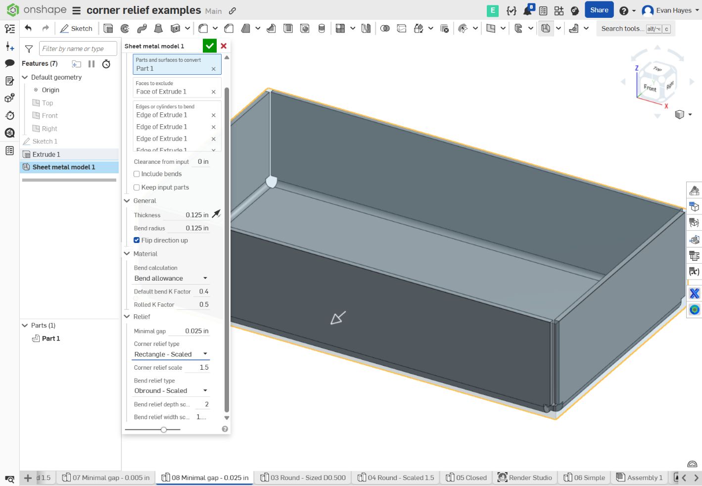
In Onshape Feature list → double-click Sheet metal model → expand Relief → Minimal gap
Open a step below to see its screenshot. Blue outlines identify the controls; select an image to open the original at full size.
1 Xeon: choose the material and thickness
Open Materials, choose the exact alloy and temper, then select the thickness you intend to cut. This example uses 5052-H32 aluminum, 0.125″. Make sure the Bending tab is selected.
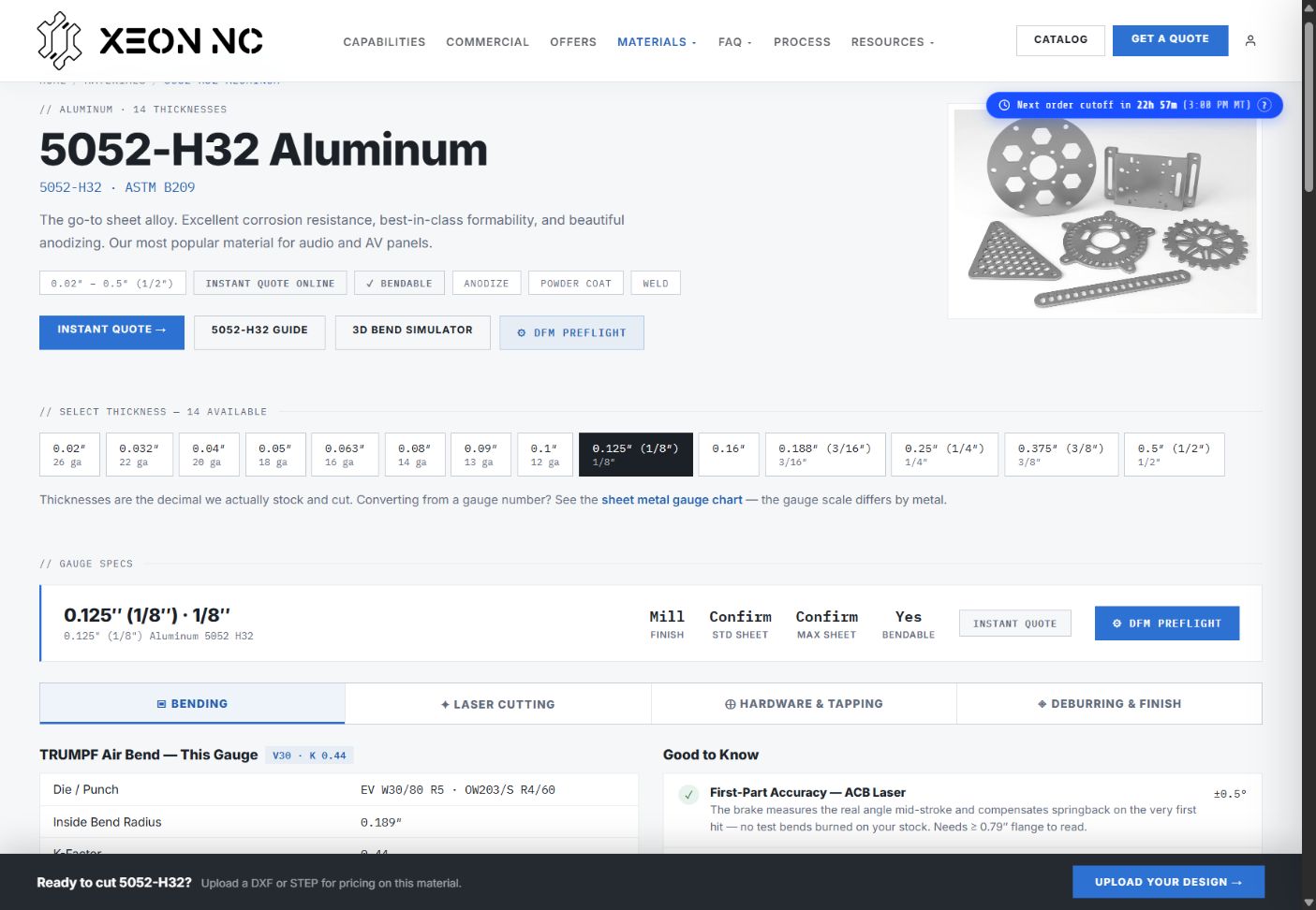
2 Xeon: open CORNER RELIEF → Learn More
In the Bending table, find Min Hole / Cutout from Outside Face. The CORNER RELIEF row is directly underneath it. Select Learn More.
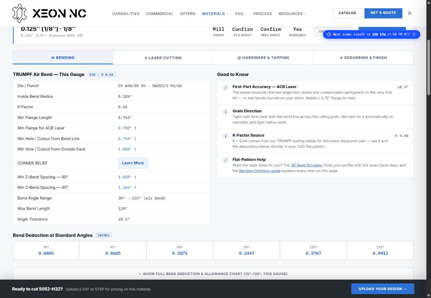
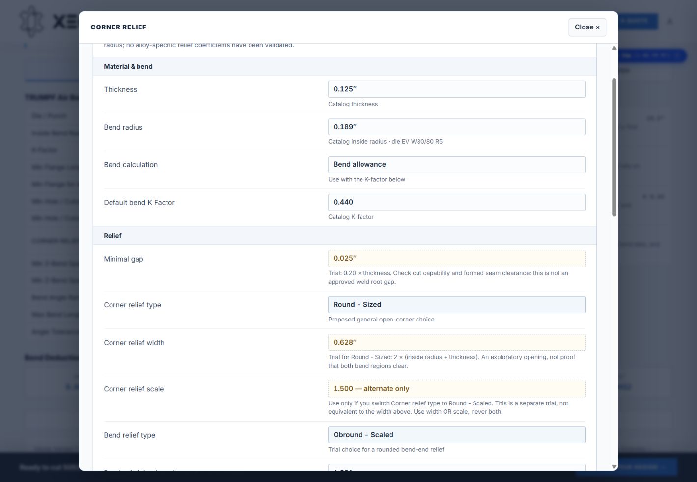
3 Xeon: read Minimal gap in Onshape setup
At the top of the popup, find Onshape setup → Relief → Minimal gap. Read the value, units and status together. For this example the displayed value is 0.025″, an experimental starting value from 0.20 × thickness.
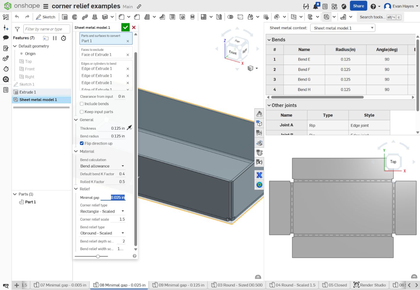
4 Onshape: Sheet metal model → Relief → Minimal gap
In the Part Studio feature list, double-click Sheet metal model (named Sheet metal model 1 here). Expand Relief if it is collapsed, then enter 0.025 in in Minimal gap for this trial. Include units and use the green checkmark to accept.
Open this material’s Onshape setup → · Compare the three gap settings → · Download the four walkthrough screenshots
Keep the example and your production setup separate. The gap-only Onshape comparison below retains its original radius and K-factor. For a new part, use the applicable catalog bend data as well as checking the gap. Changing one field does not validate the other settings.
Change the seam gap. Keep the rest fixed.
We duplicated the original box into three Part Studios and changed only Minimal gap: 0.005″, 0.025″ and 0.125″. These are screenshots captured directly from Onshape, with the same folded view for each comparison.
- Original demonstration box
- 11 × 6 × 2.5″ · 5052 aluminum example
- Thickness / inside bend radius
- 0.125″ / 0.125″
- Bend calculation / K-factor
- Bend allowance / 0.400
- Corner relief
- Rectangle – Scaled / 1.500
- Bend relief
- Obround – Scaled / depth 2.000 / width 1.063
- Rip style / wall bends
- Edge joint / four 90° bends
Controlled CAD comparison, not a forming trial. We kept the original demonstration radius and K-factor to isolate the gap change. They differ from the current 0.125″ 5052-H32 catalog setup (radius 0.189″, K-factor 0.44). This does not validate the popup’s trial gap or establish an alloy-specific minimum.
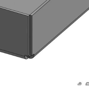
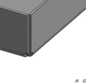
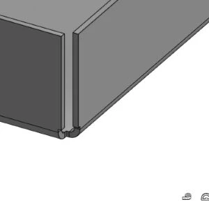
What changed: the seam between meeting wall edges opens as Minimal gap increases. The flat pattern also changes at the wall edges. All three examples regenerated into a folded box and a flat pattern.
What stayed fixed: the relief type, corner scale, thickness, radius and bend-relief controls. Keeping the controls fixed does not guarantee an identical cutout boundary: the adjacent geometry can still respond to the seam change.
What this cannot tell us: the smallest cuttable gap, crack-free forming clearance, finished seam tolerance, weld quality or collision-free brake sequence. Those require the intended process and a physical trial.
Repeat the comparison on your own part
- Duplicate the Part Studio and record its material, thickness, radius, K-factor, relief settings and joint style.
- Edit Sheet metal model → Relief → Minimal gap. Enter a value with units. Leave the other fields unchanged and accept the feature.
- Inspect every folded seam, then open Sheet metal table and flat view. Check wall edges, relief boundaries and remaining material; dimension the geometry where required.
- Check the bend sequence and tooling clearance, then cut and form a coupon. Record the actual seam gap, edge contact, cracking, bulging and weld fit-up before choosing a production value.
Saved Onshape examples: 0.005″ · 0.025″ · 0.125″. Access requires permission to the document. Onshape’s field definitions describe Minimal gap separately from corner and bend relief.
Two walls, one corner, no leftover space.
A box, an enclosure, a pan with four sides: two adjacent flanges fold 90° toward each other and their vertical edges are supposed to meet. On the flat they already share a 90° internal corner. After forming, each flange has thickness, and that thickness has to live somewhere.
Depending on the joint construction, insufficient relief can leave material that interferes as adjacent walls form. The brake stalls, the second flange walks, or the corner mushrooms. Building the clearance into the laser-cut blank is cheaper than discovering it on the press.
This is a formed collision, not a flat-pattern overlap. The blank can look perfectly legal unfolded and still crash when both walls come up. Inspect both the flat-pattern bend regions and the folded seam; they answer different clearance questions.
Choose the alloy, temper and thickness.
Open the material catalog, select a thickness, and open CORNER RELIEF below Min Hole / Cutout from Outside Face in the Bending table. It shows a proposed open-corner option, a candidate for welded fit-up, current CAD bend data and conditions that need forming review.
For example, the 0.125″ 5052-H32 page lists an inside radius of 0.189″ and K-factor 0.44 for the assigned W30 die. Its Onshape setup panel now includes clearly labeled experimental relief values. Use them for a controlled trial, not as approved production minimums.
Measure the relief and the seam separately.
- Identify both bend regions in the flat pattern; distinguish their tangent boundaries from bend centerlines.
- Measure the actual relief opening and its position relative to both bends. Check the smallest cut width and the remaining material.
- Measure the rip/seam gap in the folded corner and check the complete bend sequence for contact.
- Trial-form the selected geometry with the actual tooling. A CAD regeneration or static clearance check does not prove crack-free forming.
Use material guidance, not the retired gap calculator.
The former calculator converted a 90° bend-deduction estimate into a claimed corner minimum. That mapping was not established. Choose your material and thickness →
For unsupported tooling, substitute material data or missing inputs, request forming review rather than relying on a generated number.
Bend deduction is not a relief width.
Bend deduction helps calculate developed length. It does not by itself specify where a corner cutout must end, the size of that cutout, or the clearance between meeting edges.
Document the measurement datums, bend angles and geometry. Any future numerical recommendation needs a stated range of validated material, thickness, radius and tooling conditions.
The preview is not a collision guarantee.
Our quoting system’s 3D view is a good visual reference for the folded part. It is not a press-brake simulation, and it cannot guarantee that two perpendicular flanges will miss at the corner.
The mesh is built from the developed blank and the assigned radius. It does not model springback over-bend, coating thickness, or the last few thousandths of flange walk as the punch bottoms. A corner that looks closed-but-fine in the preview can still crash on the brake.
Use the preview to inspect the part, then check the complete forming sequence and trial-form with the actual tooling. Neither the preview nor the retired estimate guarantees clearance.
Match the bend data before sizing the corner.
Set the actual thickness and applicable inside radius. Use the selected bend-calculation method consistently. Configure the rip gap independently from the corner opening; scaled reliefs must be measured after a thickness or radius change.
There is no demonstrated universal rule that a 1× thickness corner relief is always large enough or always manufacturable.
Three controls, three different jobs.
| Control | What it sets | How to choose it |
|---|---|---|
| Minimal gap | The smallest clearance between edges defining a rip | Choose for forming and the intended seam or welding procedure. |
| Corner relief width | The opening size of a Sized corner | Establish from the actual cutout and both intersecting bend regions. |
| Corner relief scale | A dimensionless multiplier for a Scaled corner | Onshape allows 1.00–2.00; inspect the resulting opening rather than treating the value as inches. |
For 0.125″ 5052-H32, the current Xeon catalog lists radius 0.189″ and K-factor 0.44 with W30 tooling. Relief size and seam gap still require part-specific selection. Do not enter the retired 0.018″ estimate as an automatic minimum.
Onshape control definitions · Research and Xeon validation plan
Four honest options.
If the required clearance conflicts with a lid, fastener or part envelope, review the joint geometry and forming sequence. The following changes are candidates to evaluate.
Seven lines before you upload.
Use these checks to document the geometry and process before release. Physical forming validation remains part of the job.
Upload the formed STEP with the relief already in the blank.
Send the model with the material and thickness selected. We unfold against the die that will run the job. Include the intended seam gap and any welding requirements so we can review the forming setup.
Upload your STEP →