Choose the screw. Then check the sheet.
A countersink is a conical seat around a through-hole. The drawing must define both.
This walkthrough uses the actual rounded plate in Onshape: 2.320″ × 2.000″ × 0.125″, with four R0.200″ corners and one central hole. The example material is 5052-H32 aluminum. The selected fastener is a #8-32 flat-head screw with an 82° head.
Open the Xeon countersink size chart and find the #8-32 row under 82°. Transfer the listed through-hole and major diameter into CAD. A screw-size label alone does not fully specify the hole, and a CAD library preset may use different dimensions.
| Requirement | This example |
|---|---|
| Through-hole / minor diameter | Ø0.193″ — a clearance hole, not a #8-32 tapped hole |
| Countersink / major diameter | Ø0.359″ at the top surface |
| Included angle | 82° — the whole cone angle, not 41° |
| Side | Top face, as shown in the top view |
| Stock thickness | 0.125″ nominal |
Match the actual screw specification. Xeon’s standard tables cover 82° and 90° seats; specialty fasteners can use other angles. Do not substitute a 90° cone just because it is available in the CAD menu.
Leave material below the cone.
In the Xeon countersink calculator, select Inches → 82° → #8-32 → 0.125″ → Top. Read the pilot diameter, cone depth, and remaining land together.
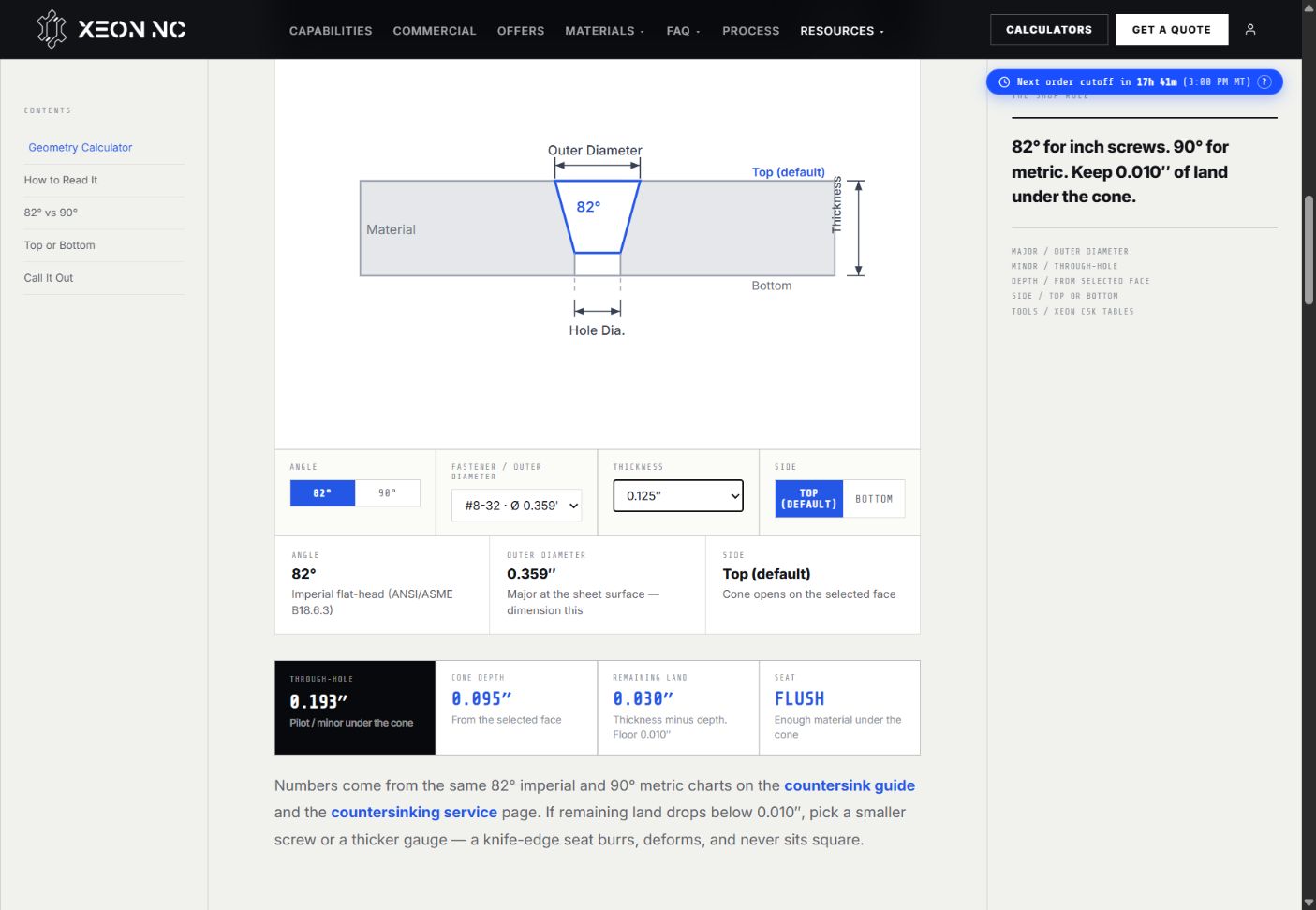
Depth h = (D − d) / [2 tan(θ / 2)]
h = (0.359 − 0.193) / [2 tan(41°)]
h = 0.095481″Remaining land = t − h = 0.029519″
Here, D is the major diameter, d is the through-hole diameter, θ is the included angle, and t is sheet thickness. This exact calculation rounds to the calculator’s displayed values. The nominal land exceeds Xeon’s 0.010″ screening minimum.
That screening result is not a strength rating or a guarantee of screw flushness. Check the actual fastener head, allowable proud/recessed condition, finish, stock variation, and diameter/angle tolerances. For a worst-case land check, use minimum thickness, maximum major diameter, minimum bore diameter, and minimum included angle within the permitted limits.
Why the next screw size can fail
Xeon’s #10-32 row uses Ø0.411″ over Ø0.199″ at 82°, with a listed depth of 0.122″. In this same 0.125″ sheet, only about 0.003″ remains. That misses the 0.010″ screen. Select a smaller fastener, thicker stock, or a different fastening method with the shop; do not silently reduce the major diameter and assume the original head will still fit.
Use a Hole feature with explicit values.
- Locate the hole. Sketch a point on the intended entry face. Constrain it to the design references. This plate uses the centered origin; the intended center is 1.160″ from the left edge and 1.000″ from the bottom edge.
- Create Hole. Select the sketch point and the correct part as the merge scope. Choose Inch, Countersink, and Drilled for this untapped bore.
- Override the hole diameter to 0.193 in. Do not leave a convenient drill-size preset controlling a different bore. Onshape may retain the original drill-size label and report that parameters were overridden; verify the actual numeric fields and resulting feature name.
- Set the cone to Ø0.359 in × 82 deg. The countersink angle is separate from a drill-tip angle. A drill-tip value such as 118° is not the countersink specification.
- Choose Through all. Start from the intended part face, check the direction, and confirm the cone opens on the top side. Through all applies to the selected merge scope.
- Accept and inspect. Rotate the model and inspect the cone and the short cylindrical land beneath it. Recheck these values after changing stock thickness or screw size.
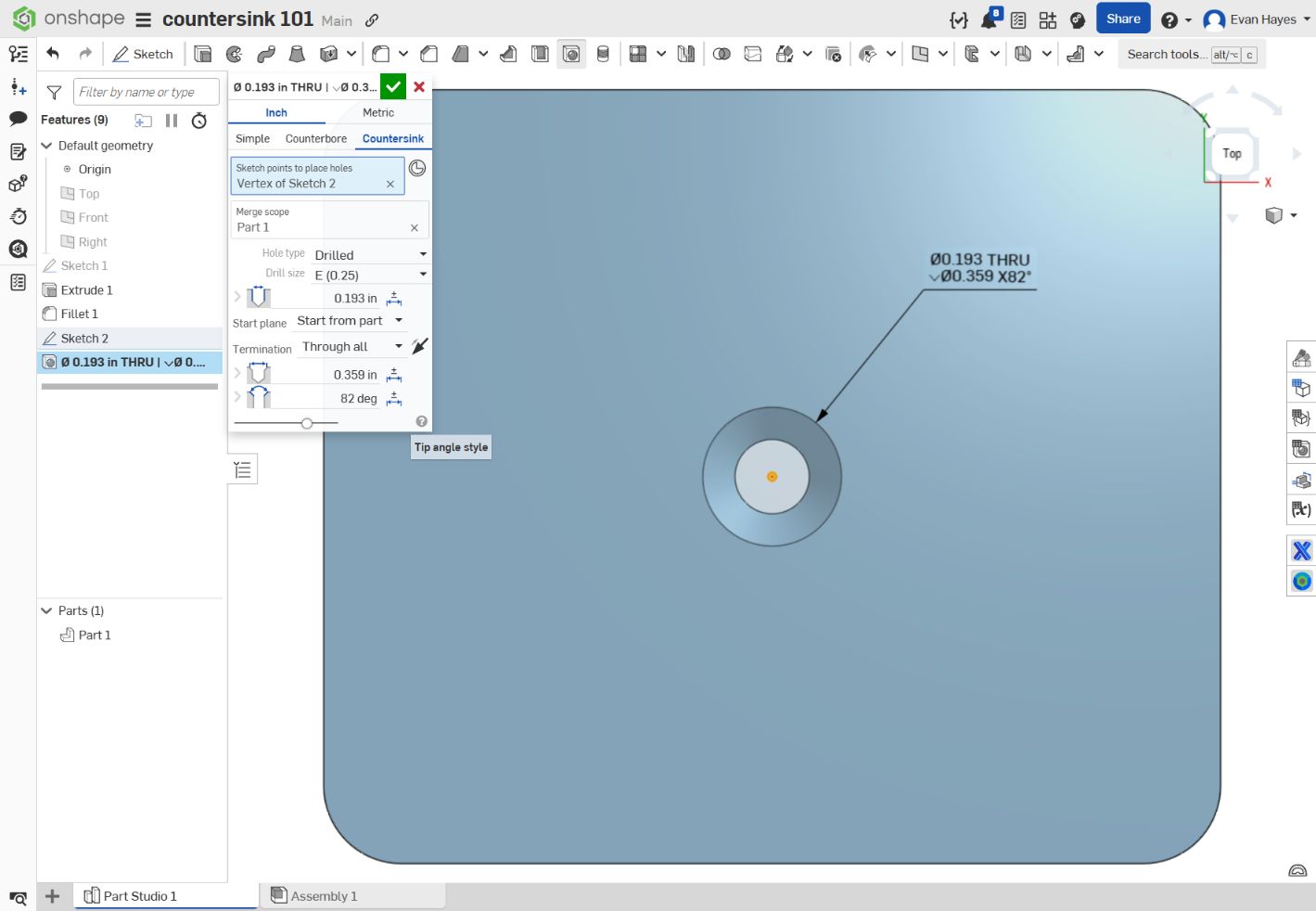
The native Hole feature also supplies information for drawing hole callouts. A visually similar Extrude Remove plus Chamfer does not provide the same native Hole metadata. See Onshape’s Hole feature documentation.
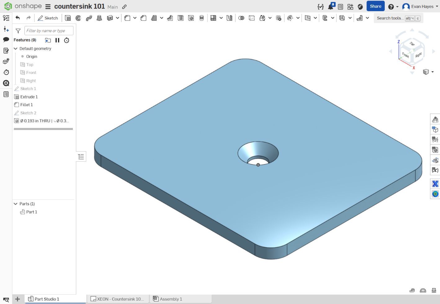
Specify the seat so it can be inspected.
Create a drawing of the part with inch units and a readable scale. Use a top view to locate the hole; add an edge view for thickness and an enlarged section through the hole when the cone needs explanation. An isometric view is useful for orientation.
⌵ Ø0.359 × 82°#8-32 identifies the mating screw. The hole is not tapped.
Use Onshape’s Hole/thread callout tool, select a circle belonging to the Hole feature, and place the leader in clear space. Check the resulting values and side against the model. A manual note is an alternative, but must be reviewed whenever the geometry changes. Onshape documents the callout workflow here.
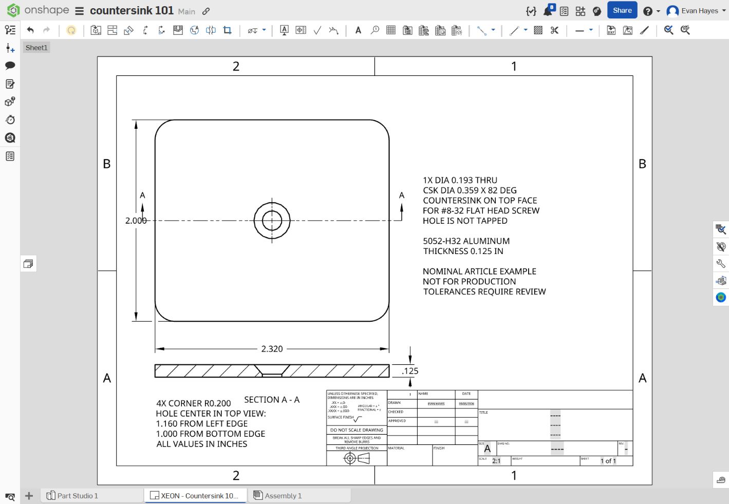
What belongs on the completed print
- Outline: 2.320″ × 2.000″, thickness 0.125″, and 4X R0.200″ corners.
- Hole location: center 1.160″ from the left straight edge and 1.000″ from the bottom straight edge in the shown top view. Choose functional references and position controls appropriate to the assembly.
- Hole specification: quantity, bore diameter and THRU, major diameter, included angle, and entry side.
- Acceptance: tolerances for sizes and location, any head flushness requirement, material and temper, finish and masking, units, drawing identity, and revision.
Dimension the major diameter at the entry surface. Cone depth is derived from the two diameters and included angle. If shown for explanation, mark depth and land as reference; avoid adding independent depth tolerances that conflict with the controlling diameters and angle.
This is a nominal teaching example, not a released production drawing. The template’s default tolerance block is not an approved specification for this part. Select functional tolerances and complete the drawing review before manufacture.
Check geometry, side, and seating.
| Check | Practical method |
|---|---|
| Bore diameter | Use suitable pins or bore measurement. Confirm the through portion remains cylindrical and clear. |
| Major diameter & angle | Use an appropriate countersink gauge or optical/profile measurement. A caliper reading across the mouth alone does not verify the cone angle. |
| Location & outline | Inspect from the defined references with a suitable fixture, optical system, or CMM. Do not measure to rounded corners as if they were straight reference edges. |
| Head seating | Check the specified screw or an agreed gauge against the allowed proud/recessed condition. This complements dimensional inspection. |
| Finish & edges | Check burrs, surface damage, coating in the seat, and the correct entry face. Agree whether dimensions apply before or after finishing. |
Keep the cutting file and finished cone distinct
If supplying a laser-cut DXF, agree with Xeon which profile the quoting workflow expects. The through-hole is Ø0.193″; the Ø0.359″ circle is the mouth of the finished countersink. Cutting the larger circle straight through removes the material needed for this cone. Identify the countersinking operation separately and supply the formed geometry in STEP plus the drawing PDF.
For a bent part, show which finished face receives the screw and how that maps to the flat blank. Check tool access, nearby bends and edges, and the manufacturing sequence with the shop. “Top” must refer to an identified view, not an unexplained screen orientation.
Release the model and drawing at the same revision. Confirm the selected tool row, actual stock thickness, and finish requirements before ordering.
Match the tool. Model the seat. Document the result.
Use the calculator for screening and the drawing for the requirements the shop will inspect.
Open countersink calculator →