Countersink fit chart.
Which flat-head screws countersink in every stocked grade and gauge, using the same tooling and rule as our material pages. A countersink seats when at least 0.010″ of material is left under the cone. Less than that and it becomes a knife edge; deeper than the sheet and it breaks through.
| Material | Finish | Thickness | Largest 82° (inch) | Largest 90° (metric) | Sizes that seat |
|---|---|---|---|---|---|
| 1100-H14 | Mill | 0.090″ | #4-40 | M4 | 5 of 16 |
| 1100-H14 | Mill | 0.125″ | #8-32 | M6 | 9 of 16 |
| 1100-H14 | Mill | 0.188″ | 1/4-28 | M8 | 14 of 16 |
| 304 | #4 Brushed | 0.024″ | — | — | 0 of 16 |
| 304 | #4 Brushed / 2B | 0.036″ | — | — | 0 of 16 |
| 304 | #4 Brushed / 2B | 0.048″ | — | M2 | 1 of 16 |
| 304 | #4 Brushed / 2B | 0.060″ | — | M2.5 | 2 of 16 |
| 304 | #4 Brushed / 2B | 0.075″ | — | M3 | 3 of 16 |
| 304 | #4 Brushed / 2B | 0.100″ | #6-32 | M4 | 6 of 16 |
| 304 | #4 Brushed / 2B | 0.120″ | #8-32 | M6 | 9 of 16 |
| 304 | #4 Brushed / 2B | 0.135″ | #10-32 | M6 | 11 of 16 |
| 304 | #1 HR Plate | 0.188″ | 1/4-28 | M8 | 14 of 16 |
| 304 | #1 HR Plate | 0.250″ | 5/16-24 | M8 | 16 of 16 |
| 304 | #1 HR Plate | 0.375″ | 5/16-24 | M8 | 16 of 16 |
| 304 | #1 HR Plate | 0.500″ | 5/16-24 | M8 | 16 of 16 |
| 304 | #1 HR Plate | 0.625″ | 5/16-24 | M8 | 16 of 16 |
| 316 | 2B | 0.036″ | — | — | 0 of 16 |
| 316 | 2B | 0.048″ | — | M2 | 1 of 16 |
| 316 | 2B | 0.060″ | — | M2.5 | 2 of 16 |
| 316 | 2B | 0.075″ | — | M3 | 3 of 16 |
| 316 | 2B | 0.100″ | #6-32 | M4 | 6 of 16 |
| 316 | 2B | 0.120″ | #8-32 | M6 | 9 of 16 |
| 316 | 2B | 0.135″ | #10-32 | M6 | 11 of 16 |
| 316 | #1 HR Plate | 0.188″ | 1/4-28 | M8 | 14 of 16 |
| 316 | #1 HR Plate | 0.250″ | 5/16-24 | M8 | 16 of 16 |
| 316 | #1 HR Plate | 0.375″ | 5/16-24 | M8 | 16 of 16 |
| 5052-H32 | Mill | 0.020″ | — | — | 0 of 16 |
| 5052-H32 | Mill | 0.032″ | — | — | 0 of 16 |
| 5052-H32 | Mill | 0.040″ | — | M2 | 1 of 16 |
| 5052-H32 | Mill | 0.050″ | — | M2 | 1 of 16 |
| 5052-H32 | Mill | 0.063″ | — | M3 | 3 of 16 |
| 5052-H32 | Mill | 0.080″ | — | M3 | 3 of 16 |
| 5052-H32 | Mill | 0.090″ | #4-40 | M4 | 5 of 16 |
| 5052-H32 | Mill | 0.100″ | #6-32 | M4 | 6 of 16 |
| 5052-H32 | Mill | 0.125″ | #8-32 | M6 | 9 of 16 |
| 5052-H32 | Mill | 0.160″ | #10-32 | M6 | 11 of 16 |
| 5052-H32 | Mill | 0.188″ | 1/4-28 | M8 | 14 of 16 |
| 5052-H32 | Mill | 0.250″ | 5/16-24 | M8 | 16 of 16 |
| 5052-H32 | Mill | 0.375″ | 5/16-24 | M8 | 16 of 16 |
| 5052-H32 | Mill | 0.500″ | 5/16-24 | M8 | 16 of 16 |
| 6061-T6 | Mill | 0.032″ | — | — | 0 of 16 |
| 6061-T6 | Mill | 0.040″ | — | M2 | 1 of 16 |
| 6061-T6 | Mill | 0.050″ | — | M2 | 1 of 16 |
| 6061-T6 | Mill | 0.063″ | — | M3 | 3 of 16 |
| 6061-T6 | Mill | 0.090″ | #4-40 | M4 | 5 of 16 |
| 6061-T6 | Mill | 0.100″ | #6-32 | M4 | 6 of 16 |
| 6061-T6 | Mill | 0.125″ | #8-32 | M6 | 9 of 16 |
| 6061-T6 | Mill | 0.188″ | 1/4-28 | M8 | 14 of 16 |
| 6061-T6 | Mill | 0.250″ | 5/16-24 | M8 | 16 of 16 |
| 6061-T6 | Mill | 0.375″ | 5/16-24 | M8 | 16 of 16 |
| 6061-T6 | Mill | 0.500″ | 5/16-24 | M8 | 16 of 16 |
| 6061-T6 | Mill | 0.625″ | 5/16-24 | M8 | 16 of 16 |
| 6061-T6 | Mill | 0.750″ | 5/16-24 | M8 | 16 of 16 |
| 7075-T6 | Mill | 0.080″ | — | M3 | 3 of 16 |
| 7075-T6 | Mill | 0.100″ | #6-32 | M4 | 6 of 16 |
| 7075-T6 | Mill | 0.125″ | #8-32 | M6 | 9 of 16 |
| 7075-T6 | Mill | 0.160″ | #10-32 | M6 | 11 of 16 |
| 7075-T6 | Mill | 0.190″ | 1/4-28 | M8 | 14 of 16 |
| 7075-T6 | Mill | 0.250″ | 5/16-24 | M8 | 16 of 16 |
| 7075-T6 | Mill | 0.375″ | 5/16-24 | M8 | 16 of 16 |
| 7075-T6 | Mill | 0.500″ | 5/16-24 | M8 | 16 of 16 |
| 7075-T6 | Mill | 0.750″ | 5/16-24 | M8 | 16 of 16 |
| 7075-T6 | Mill | 1.000″ | 5/16-24 | M8 | 16 of 16 |
| A1008 cold rolled | CR Mill | 0.024″ | — | — | 0 of 16 |
| A1008 cold rolled | CR Mill | 0.030″ | — | — | 0 of 16 |
| A1008 cold rolled | CR Mill | 0.036″ | — | — | 0 of 16 |
| A1008 cold rolled | CR Mill | 0.048″ | — | M2 | 1 of 16 |
| A1008 cold rolled | CR Mill | 0.060″ | — | M2.5 | 2 of 16 |
| A1008 cold rolled | CR Mill | 0.075″ | — | M3 | 3 of 16 |
| A1008 cold rolled | CR Mill | 0.090″ | #4-40 | M4 | 5 of 16 |
| A1008 cold rolled | CR Mill | 0.100″ | #6-32 | M4 | 6 of 16 |
| A1008 cold rolled | CR Mill | 0.120″ | #8-32 | M6 | 9 of 16 |
| A1008 cold rolled | CR Mill | 0.135″ | #10-32 | M6 | 11 of 16 |
| A1008 electro-galvanized | Electro-Galv | 0.024″ | — | — | 0 of 16 |
| A1008 electro-galvanized | Electro-Galv | 0.036″ | — | — | 0 of 16 |
| A1008 electro-galvanized | Electro-Galv | 0.048″ | — | M2 | 1 of 16 |
| A1008 electro-galvanized | Electro-Galv | 0.060″ | — | M2.5 | 2 of 16 |
| A1008 electro-galvanized | Electro-Galv | 0.075″ | — | M3 | 3 of 16 |
| A36 HR pickled & oiled | P&O | 0.060″ | — | M2.5 | 2 of 16 |
| A36 HR pickled & oiled | P&O | 0.075″ | — | M3 | 3 of 16 |
| A36 HR pickled & oiled | P&O | 0.100″ | #6-32 | M4 | 6 of 16 |
| A36 HR pickled & oiled | P&O | 0.120″ | #8-32 | M6 | 9 of 16 |
| A36 HR pickled & oiled | P&O | 0.135″ | #10-32 | M6 | 11 of 16 |
| A36 HR pickled & oiled | P&O | 0.188″ | 1/4-28 | M8 | 14 of 16 |
| A36 HR pickled & oiled | P&O | 0.250″ | 5/16-24 | M8 | 16 of 16 |
| A36 HR pickled & oiled | P&O | 0.375″ | 5/16-24 | M8 | 16 of 16 |
| A36 HR pickled & oiled | P&O | 0.500″ | 5/16-24 | M8 | 16 of 16 |
| A36 mill finish | Mill Scale | 0.060″ | — | M2.5 | 2 of 16 |
| A36 mill finish | Mill Scale | 0.075″ | — | M3 | 3 of 16 |
| A36 mill finish | Mill Scale | 0.100″ | #6-32 | M4 | 6 of 16 |
| A36 mill finish | Mill Scale | 0.120″ | #8-32 | M6 | 9 of 16 |
| A36 mill finish | Mill Scale | 0.135″ | #10-32 | M6 | 11 of 16 |
| A36 mill finish | Mill Scale | 0.188″ | 1/4-28 | M8 | 14 of 16 |
| A36 mill finish | Mill Scale | 0.250″ | 5/16-24 | M8 | 16 of 16 |
| A36 mill finish | Mill Scale | 0.313″ | 5/16-24 | M8 | 16 of 16 |
| A36 mill finish | Mill Scale | 0.375″ | 5/16-24 | M8 | 16 of 16 |
| A36 mill finish | Mill Scale | 0.500″ | 5/16-24 | M8 | 16 of 16 |
| A36 mill finish | Mill Scale | 0.625″ | 5/16-24 | M8 | 16 of 16 |
| A36 mill finish | Mill Scale | 0.750″ | 5/16-24 | M8 | 16 of 16 |
| AR500 | Mill | 0.250″ | Not offered | ||
| AR500 | Mill | 0.375″ | Not offered | ||
| AR500 | Mill | 0.500″ | Not offered | ||
| Corten (weathering) | Mill | 0.060″ | — | M2.5 | 2 of 16 |
| Corten (weathering) | Mill | 0.075″ | — | M3 | 3 of 16 |
| Corten (weathering) | Mill | 0.100″ | #6-32 | M4 | 6 of 16 |
| Corten (weathering) | Mill | 0.135″ | #10-32 | M6 | 11 of 16 |
| Corten (weathering) | Mill | 0.188″ | 1/4-28 | M8 | 14 of 16 |
| Corten (weathering) | Mill | 0.250″ | 5/16-24 | M8 | 16 of 16 |
| G90 galvanized | Hot-Dip Galv | 0.024″ | — | — | 0 of 16 |
| G90 galvanized | Hot-Dip Galv | 0.036″ | — | — | 0 of 16 |
| G90 galvanized | Hot-Dip Galv | 0.048″ | — | M2 | 1 of 16 |
| G90 galvanized | Hot-Dip Galv | 0.060″ | — | M2.5 | 2 of 16 |
| G90 galvanized | Hot-Dip Galv | 0.135″ | #10-32 | M6 | 11 of 16 |
| HSLAS Grade 50 | Mill | 0.188″ | 1/4-28 | M8 | 14 of 16 |
| HSLAS Grade 50 | Mill | 0.250″ | 5/16-24 | M8 | 16 of 16 |
| HSLAS Grade 50 | Mill | 0.313″ | 5/16-24 | M8 | 16 of 16 |
| MIC-6 cast plate | Machined Plate | 0.250″ | Not offered | ||
| Spring steel 1075 / 1095 | Annealed / Hardened | 0.005″ | Not offered | ||
Leave the land.
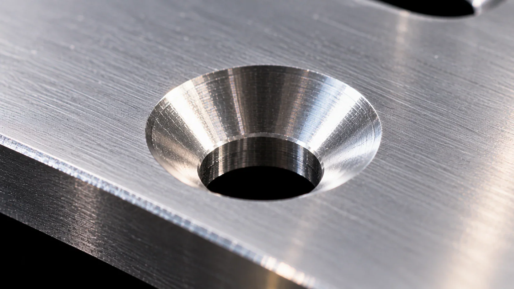
A countersink is a cone cut to the screw head's angle, ending in a straight through-hole. What decides whether it works is the material left under the cone — the land.
Land = sheet thickness − cone depth. With at least 0.010″ of land the head seats flush and square. With less, the bottom of the cone becomes a razor ring that burrs, deforms under the screw and never seats. If the cone is deeper than the sheet, it cuts out the far face and the head pulls through.
On the chart every horizontal line is a countersink at its cone depth, and every vertical line is a gauge we stock in the grade you chart. Where they cross, the dot says whether that screw seats at that gauge. The green region is safe; the amber band is the knife edge; above the top line the cone breaks through.
Inch flat heads
Standard ANSI flat-head machine screws use an 82° head. Our 82° series runs from #4-40 to 5/16″, with cone depths of 0.072″ to 0.194″.
ISO metric flat heads
ISO metric flat heads (DIN 965 / ISO 7046 style) use 90°. Our 90° series runs from M2 to M8. 100° rivet and aerospace countersinks are available on request.
Held depth
Depth is held to ±0.003″ with controlled depth stops, so a gauge that leaves the full land on the chart leaves it on the part.
The thinnest gauge each screw needs.
Minimum sheet = cone depth + 0.010″. The last column is the thinnest gauge we stock, in any grade that offers countersinking, that meets it.
| Screw | Angle | CS ⌀ | Cone depth | Min sheet | Thinnest stock gauge |
|---|---|---|---|---|---|
| #4-40 | 82° | 0.255″ | 0.072″ | 0.082″ | 0.090″ |
| #6-32 | 82° | 0.307″ | 0.082″ | 0.092″ | 0.100″ |
| #8-32 | 82° | 0.359″ | 0.095″ | 0.105″ | 0.120″ |
| #10-24 | 82° | 0.411″ | 0.122″ | 0.132″ | 0.135″ |
| #10-32 | 82° | 0.411″ | 0.122″ | 0.132″ | 0.135″ |
| 1/4-20 | 82° | 0.531″ | 0.159″ | 0.169″ | 0.188″ |
| 1/4-28 | 82° | 0.531″ | 0.159″ | 0.169″ | 0.188″ |
| 5/16-18 | 82° | 0.656″ | 0.194″ | 0.204″ | 0.250″ |
| 5/16-24 | 82° | 0.656″ | 0.194″ | 0.204″ | 0.250″ |
| M2 | 90° | 0.157″ | 0.029″ | 0.039″ | 0.040″ |
| M2.5 | 90° | 0.197″ | 0.047″ | 0.057″ | 0.060″ |
| M3 | 90° | 0.236″ | 0.053″ | 0.063″ | 0.063″ |
| M4 | 90° | 0.315″ | 0.076″ | 0.086″ | 0.090″ |
| M5 | 90° | 0.394″ | 0.096″ | 0.106″ | 0.120″ |
| M6 | 90° | 0.472″ | 0.109″ | 0.119″ | 0.120″ |
| M8 | 90° | 0.630″ | 0.155″ | 0.165″ | 0.188″ |
Not offered: MIC-6 cast plate, AR500, Spring steel 1075 / 1095. Full countersink dimensions are in the countersink size chart; for any angle and diameter, use the countersink calculator.