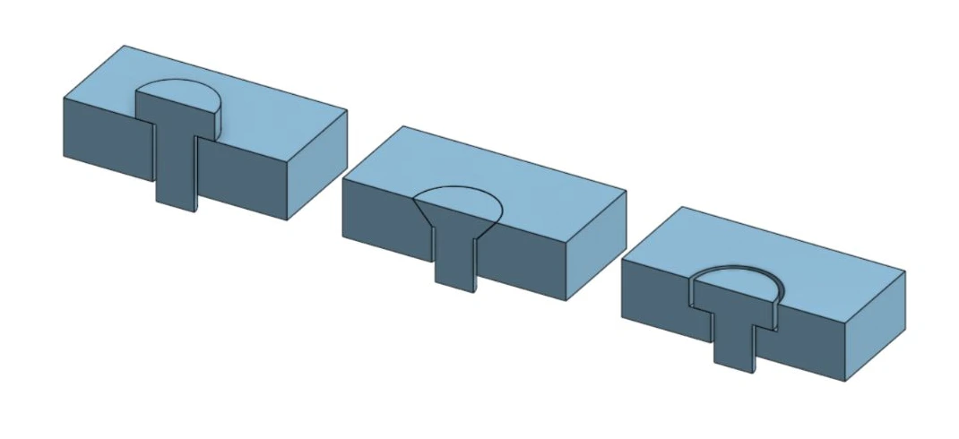
A small recess. A useful difference.
A screw head can be the tallest feature on an otherwise flat panel. Countersinking creates a conical seat that lets a compatible flat-head fastener finish at the surface. That small change can solve a clearance problem, simplify a mating interface, or give a visible assembly a more deliberate finish.
The useful question is where the head needs to live. Picture a removable cover sliding beneath a second panel: a projecting head consumes some of the gap. Recessing the head into the cover can recover that space, provided the cover has enough material for the seat.
Keep the working face clear.
On covers, brackets, and fixture plates, a flush head can let an adjacent component pass over the fastener location. Check the entire assembly: the screw tip, nut, and driver still need room on their respective sides.
Let the surfaces meet.
A recessed head can remove a local obstruction between stacked parts. When that interface matters, define an allowable head projection or recess and inspect it after assembly; the word “flush” alone leaves room for interpretation.
Make the hardware part of the design.
On a front panel or access door, flat-head screws give a consistent surface profile. Plan the finish, hardware color, drive access, and replacement process together. A neat recess will not conceal a damaged screw drive.
The taper also tends to center the head in its seat as the joint is tightened. That is useful when the mating hole pattern is correct, but it reduces the freedom available from an ordinary clearance hole. Multiple countersunk screws can compete for position if the patterns do not line up. Use dedicated locating features when precise alignment is required.
Match the seat to the screw.
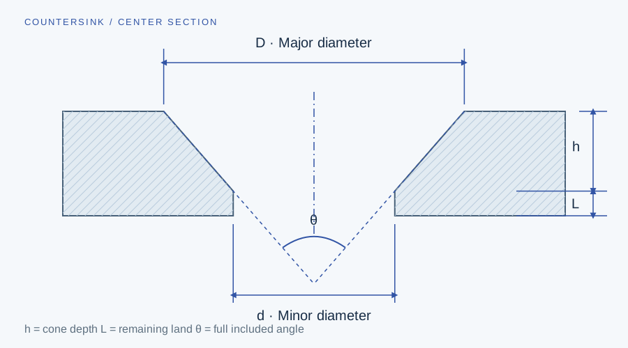
A countersink is an enlarged, tapered opening at one end of a hole. Its major diameter D is measured at the surface. Its minor diameter d is the cylindrical hole below the taper. The included angle θ is the full angle between the two sloping sides in a section through the center.
Start with the exact fastener specification. The head angle, head diameter, body clearance, and head-height tolerances all influence seating. The thread designation alone does not fully define the recess.
These are common families, not a rule for every screw. Other angles exist. KAR’s tooling catalog distinguishes 82°, 90°, and 100° cutters by application. Verify the purchased hardware rather than choosing an angle from the unit system alone.
For a matching-angle screw, making the seat too small leaves the head proud; making it larger allows the head to sit farther below the face. Changing the angle is a different problem: the surfaces no longer mate over the intended area. Extra tightening is not a substitute for matching the geometry.
Three openings. Three different jobs.
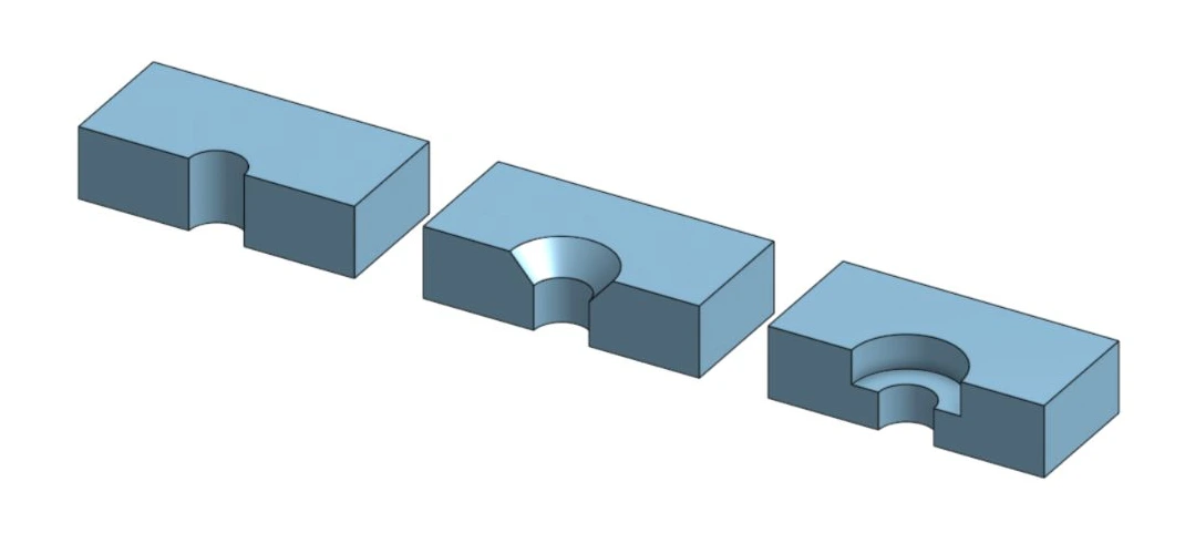
| Feature | Shape | Typical purpose |
|---|---|---|
| Clearance hole | Straight opening | Pass the fastener body through the part; the head remains above the face. |
| Countersink | Conical seat | Recess a matching tapered flat head. |
| Counterbore | Cylindrical pocket with a flat shoulder | Recess a compatible flat-bearing head, such as a socket-head cap screw. |
A counterbore needs enough depth for the chosen head and enough material beneath its shoulder. A countersink uses a taper instead, but it still removes supporting material. Compare the actual screw envelopes before deciding which feature can fit your stock.
A light edge break is another separate operation. It removes the sharp rim or burr at a hole entrance. It does not define a full fastener seat. If your goal is edge quality rather than head clearance, specify that requirement directly and consult the deburring guide.
The underside sets the limit.
The recess must fit within the material while leaving enough support below the taper. For an ideal conical seat, calculate its depth from the two diameters and the included angle:
Remaining cylindrical land: L = t − h, where t is the material thickness. Use the same length units throughout.
For Xeon’s listed #8-32, 82° seat, D is 0.359 in and d is 0.193 in. The ideal depth is approximately 0.0955 in; the tooling chart rounds it to 0.095 in. In 0.125-inch stock, the calculated land is about 0.0295 in.
One countersink. Three outcomes.
The hole diameters and angle stay fixed.
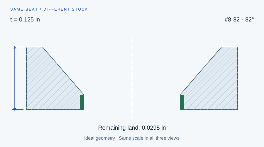
About 0.0295 in remains. This clears the tooling-data screen; joint strength and tolerances still need review.
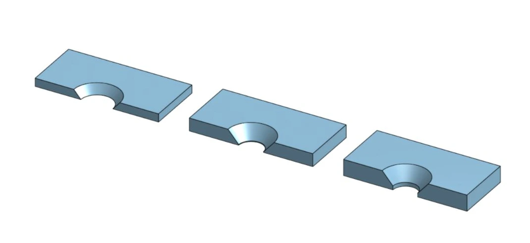
Xeon’s countersink size chart uses a 0.010-inch minimum land for its thickness screening. Passing that screen does not establish the strength of a joint. Stock tolerance, machining tolerance, local loading, material condition, and installation torque still need consideration. Use the countersink calculator to inspect a different diameter or angle.
If the cone breaks through, its underside opening grows beyond the intended minor diameter. If it almost breaks through, very little cylindrical support remains. Neither condition is fixed by forcing the screw deeper. Consider a smaller suitable fastener, thicker stock, a different head style, or a separately engineered attachment. Formed dimples and special thin-sheet fasteners require their own design and process review.
Look beyond one hole.
Measure edge distance from the larger opening.
The surface recess occupies more space than the through hole. For a straight outside edge, the nominal surface ligament is the center-to-edge distance minus D/2. Between equal adjacent countersinks, it is the center spacing minus D. Those calculations show what remains geometrically; they do not supply a universal acceptable minimum.
Check bends and tool access.
A recess near a bend can overlap the forming region or be difficult to reach after bending. Show which face receives the countersink and review the operation sequence. The drawing and formed model should make that face unambiguous even when the part is flipped.
Include the final coating.
Coating on the conical seat changes the contact surface. If head position is functional or cosmetic, define whether the requirement applies before or after finishing and discuss masking or another process allowance. Do not assume a universal oversize correction for every coating and screw.
Decide which features locate the assembly.
If two plates must slide into adjustment before tightening, a pattern of countersunk screws may work against that intent. Decide where position comes from, where clearance is permitted, and where clamping happens. A flush appearance alone does not answer those assembly questions.
Give the shop the whole feature.
In Onshape, the Hole feature supports simple, countersunk, and counterbored holes. Select the location, correct starting face, hole style, diameter, countersink diameter, and angle. Review the termination and affected parts, then inspect a section through the hole. See the official Onshape Hole documentation for the feature controls.
When you need a step-by-step example, follow Xeon’s Countersinks in Onshape: Model, Check & Draw. Use its workflow with your current fastener and stock, and review generated hole callouts against the model.
CSK ⌀0.359 × 82°
ON FACE A
Illustrative #8-32 seat geometry from Xeon’s table. Locate all four holes, identify Face A, and add the required tolerances and head-position requirement before release.
A two-dimensional cut profile cannot fully communicate a countersink’s taper or side. Follow the quote workflow for assigning secondary operations and include the supporting model or drawing as required. Keep the files, quantities, material, thickness, and revision consistent.
- Identify the hardware. Record the exact fastener and the head geometry that governs the seat.
- Check the section. Confirm the through hole, major diameter, included angle, depth, and remaining land.
- Check the neighborhood. Review edges, nearby holes, bends, mating surfaces, and driver access.
- Define acceptance. State the countersink side, tolerances, finish condition, and allowable head position.
- Review the first assembly. Check the intended hardware against the finished part and the actual mating components.
Before you choose flush hardware.
Does countersinking make a joint stronger?
Do not assume it does. The recess removes material and changes how the head bears on the part. Joint performance depends on the material, remaining section, fastener, preload, and loading. Choose it for an identified function and assess strength separately.
Can I put an 82° screw in a 90° countersink?
The head and seat have different slopes, so they cannot make the intended full conical contact. Match the specified head angle rather than trying to compensate with diameter or tightening torque.
How deep should the countersink be?
Start with the specified major diameter, minor diameter, and included angle. Calculate the nominal cone depth, check the remaining material, and set tolerances that achieve the required assembled head position with the chosen hardware.
Can any thin sheet be countersunk?
No. The required seat may consume most or all of the thickness. Check the geometry before selecting the process. A smaller compatible head, different stock, or a redesigned attachment may be necessary.
Does a flush head make the assembly sealed?
No. A countersink defines a mechanical seat, not a fluid seal. Any sealing requirement needs a separately specified and validated sealing arrangement.
Models & references
The cutaway models were created for this article in Xeon’s Onshape document on September 18, 2026. Captures are cropped from the CAD viewport. These are geometric examples, not physical test results; simplified fasteners illustrate seating rather than a complete hardware specification.
The dimensioned section and thickness selector use ideal cone geometry and Xeon’s published tooling table. Model controls and hole terminology: Onshape Hole reference. Common cutter-angle families: KAR counterbore and countersink catalog.
Related reading: SendCutSend’s benefits of countersinking article. Xeon dimensions and screening criteria in this article come from Xeon’s own tooling data.
Make room for a better fit.
Check your seat geometry, then specify the countersink face and fastener requirements with your part.