Stiffness Comes from Shape: Designing Lighter Sheet Metal Parts
Start with the movement the assembly can tolerate
A bracket can remain below its material yield strength and still move far enough to misalign a sensor. A cover can carry its service load and still feel flexible when someone presses its center. In both cases, the part may satisfy a strength check while failing its functional requirement.
Start the design review with a measurable statement: identify the force, where it acts, its direction, and the maximum permitted displacement at a named location. Include relevant handling, transport, and installation loads. An equipment shelf may have one requirement for its working load and another for temporary loading near its front edge.
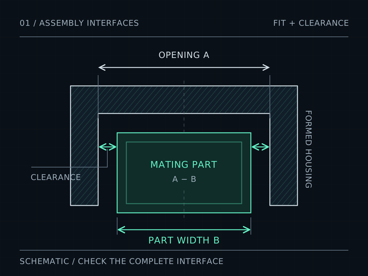
Then draw the supports. Mark which surfaces contact the assembly and which fasteners prevent translation or rotation. A model with an entire edge fixed represents a different structure from a panel attached by two screws. The stiffness target belongs to that installed arrangement.
Separate material strength from structural stiffness
In a linear elastic beam model, bending rigidity is the product E × I. Young’s modulus, E, describes the material’s elastic response. The second moment of area, I, describes how the cross-sectional area is distributed about the bending axis. A yield-strength value does not supply either the section geometry or a deflection prediction. Virginia Tech’s beam experiment notes explain this distinction through the relationship between bending moment and displacement.
Strength assessment asks whether a relevant failure limit is reached. Stiffness assessment asks how far the structure moves under load. Both are necessary when movement affects alignment, sealing, clearances, or the appearance of an enclosure.
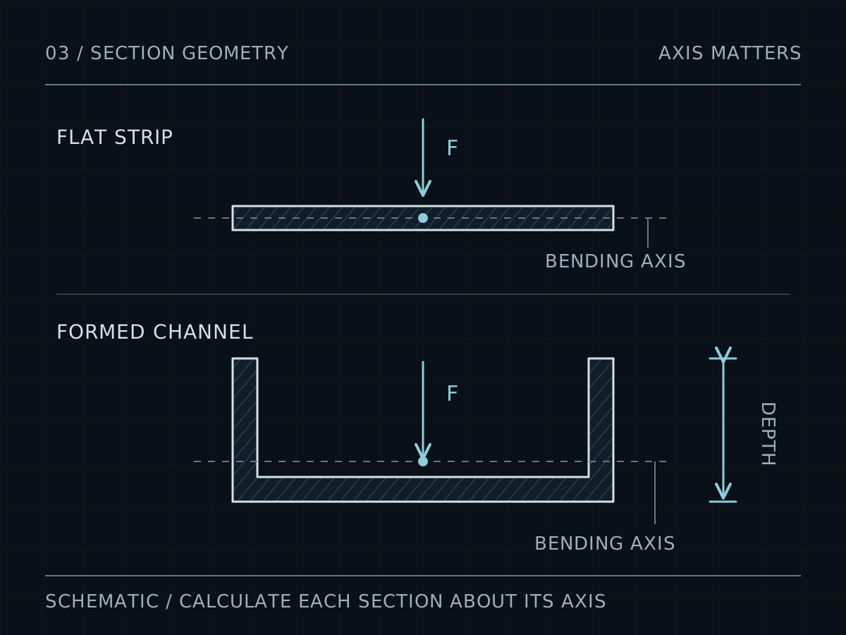
For a flat rectangular strip bending through its thickness, I = b × t³ / 12, where b is its width and t is its thickness. Orient the same rectangle differently and the result changes. Always state the bending axis; an unlabeled section-property number is incomplete. The rectangular-section expression is derived in MIT’s structural mechanics problem solutions.
A calculation that makes the tradeoff visible
Consider a uniform strip 100 mm wide, 2 mm thick, with a 200 mm unsupported length. Assume E = 200,000 N/mm². Idealize it as a cantilever with a perfectly rigid, full-width clamp and a total transverse load of 10 N at its free end, distributed across the width to avoid a corner-load effect.
Use a linear elastic, small-deflection Euler–Bernoulli beam approximation. Neglect self-weight, shear deformation, clamp compliance, local contact effects, and plate behavior across the width. These assumptions make this a comparison example, not a qualification of a real bracket.
For this load case, tip deflection δ = F × L³ / (3 × E × I). The root bending moment is F × L, and nominal extreme-fiber stress is σ = F × L × (t / 2) / I. MIT’s cantilever lecture derives the tip-deflection relation and its fixed-end boundary conditions.
| Configuration | I | Tip movement | Nominal root stress |
|---|---|---|---|
| 200 mm span; 2 mm thickness | 66.67 mm⁴ | 2.00 mm | 30.0 MPa |
| 100 mm span; 2 mm thickness | 66.67 mm⁴ | 0.25 mm | 15.0 MPa |
| 200 mm span; 3 mm thickness | 225.00 mm⁴ | 0.593 mm | 13.3 MPa |
The 3 mm strip has 1.5 times the material mass of the 2 mm strip at unchanged width and length. Halving the idealized unsupported span reduces tip movement to one eighth. These values are calculations from the stated inputs; they are not measured Xeon results. No allowable material stress or factor of safety has been assigned.
Compare the idealized strip.
Use the same rectangular cantilever model to see how length, thickness, width, modulus, and load affect movement. The tool assumes a rigid full-width clamp, a transverse end load distributed across the width, and linear elastic small-deflection behavior.
This is a screening calculation, not a strength approval. It does not model holes, joint flexibility, bend radii, local buckling, fatigue, or material yield. A formed section requires its own section properties and load model.
Put material where it resists the required bending
A flat blank and a folded channel can use similar amounts of material while placing that material differently relative to the bending axis. Moving area away from the neutral axis can increase the relevant second moment of area. That is the reason to investigate flanges, formed ribs, and deeper sections before increasing thickness throughout a part.
Calculate the final section, including its centroid and the intended axis. For a section assembled from simple areas, the parallel-axis approach sums each area’s own second moment plus its area multiplied by the square of its offset. Bend radii and cutouts may need explicit treatment. MIT’s general beam notes provide the section-property framework.
Compare at a consistent functional envelope. A taller flange may occupy cable space, obstruct a connector, or change an assembly interface. A return flange can help restrain a free edge, but it also changes the section and manufacturing sequence. Record its depth and location; do not attach a generic improvement factor to the word “flange.”
Shorten the unsupported path and inspect the connection
The span calculation is a reason to examine mounting locations early. Bringing support closer to a load can be useful when the surrounding assembly permits it. A rib that ends before the mounting region, however, still needs to transfer its load through the remaining sheet.
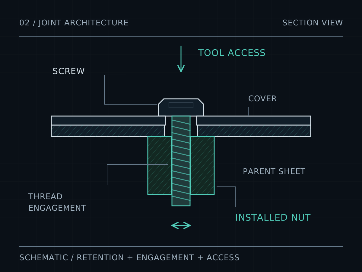
Trace that path from the applied force into the supporting structure. Look for narrow necks, interrupted flanges, fastener slots, and flexible mounting tabs. A locally thick or deep section cannot eliminate movement caused by rotation at its attachment.
For prototype evaluation, measure the functional point relative to the supporting assembly. A second measurement near the mount helps distinguish attachment movement from bending of the part. Record the hardware and installation condition with the result. Virginia Tech’s experimental guidance emphasizes checking boundary assumptions and measurement uncertainty alongside the predicted response.
Check twisting, local buckling, and openings
Good bending performance about one axis does not establish torsional performance. An open channel loaded away from its shear center can twist. A closed section has a different torsional load path, and a seam or removable cover must transfer the required shear before it can be credited as structural closure. MIT treats open-section torsion and closed-section torsion separately for this reason.
Thin walls also need a stability check. Increasing section depth can leave a slender compressed wall that buckles locally. Wall width, thickness, edge restraint, stress distribution, and imperfections matter. A bending stress below yield alone does not resolve this question. See MIT’s plate-buckling notes.
Evaluate perforations in their actual locations. Open-area percentage does not describe whether a vent pattern cuts through a critical flange, leaves narrow ligaments, or interrupts a connection. Analyze the remaining geometry. For complex panels, choose a plate or shell model that represents the openings, supports, and load distribution, then check the important response in the assembled prototype.
Make the stiffness feature accessible to the tooling
Review the proposed section with its forming sequence. Establish the material and condition, inside bend radius, die opening, flange length, and available punch clearance. A return that looks straightforward in the finished model may obstruct a later bend or prevent removal from the tooling.
A short flange also needs enough support during forming. SSAB’s flange-height guidance explains why minimum flange dimensions depend on the bending setup. Apply the fabricator’s confirmed requirements to the actual material and tools.
Carry this review into the flat pattern. Locate reliefs and nearby holes with the bend zones in mind, and retain the critical finished dimensions on the drawing. Use the sheet metal bending guide and tooling selection guide when preparing that discussion.
Release the load case with the part
A lighter design is ready for release when its performance requirement and verification method are as clear as its geometry. Include the following in the review:
- Function: named load cases, force locations, directions, and allowable movement at the functional interfaces.
- Structure: material condition, minimum thickness basis, section axes, supports, fasteners, and connection assumptions.
- Failure modes: deflection, nominal and local stress, buckling, twisting, and fatigue where repeated loading matters.
- Manufacturing: confirmed bend radii, flange lengths, reliefs, tool access, forming sequence, and inspection datums.
- Evidence: calculation or simulation inputs, limits of the model, prototype setup, measured response, and acceptance criteria.
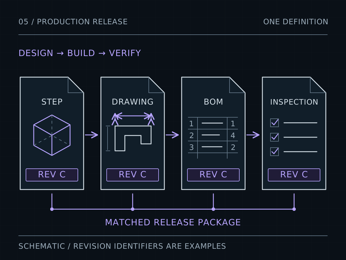
If the unloaded part is already distorted, establish that starting geometry before comparing loaded movement with the model. The laser-cut warping guide addresses that separate process question. Keep the released drawing, analysis, and verification record tied to the same revision.
Sources & further reading.
Manufacturer data and technical references support the principles above. Worked scenarios are illustrative design studies. Confirm product-specific requirements against the selected material, hardware, and manufacturing route.
- Virginia Tech — Static Deflection of a Beam
Elastic bending rigidity, boundary conditions, and experimental verification.
- MIT — Euler–Bernoulli Beams: Bending, Buckling, and Vibration
Cantilever end-load deflection and fixed-end boundary conditions; basis for the original numerical example.
- MIT — Structural Mechanics, Problem Set 4 Solutions
Second moment of area for a rectangular section.
- MIT — General Beam Theory
Section properties and the effect of cross-sectional geometry on bending response.
- MIT — Pure Twist, Open Section
Thin-walled open-section torsion.
- MIT — Pure Twist, Closed Section
Closed-section torsion and shear flow.
- MIT — Plate Buckling
Effects of plate geometry and edge restraint on local stability.
- SSAB — Flange Height
Minimum flange height is tied to support in the bending setup.
Connect this decision to the next.
Bring the interface into the quote.
Include your model, drawing, material, finish, and the dimensions that control the assembly.
Start a quote ↗