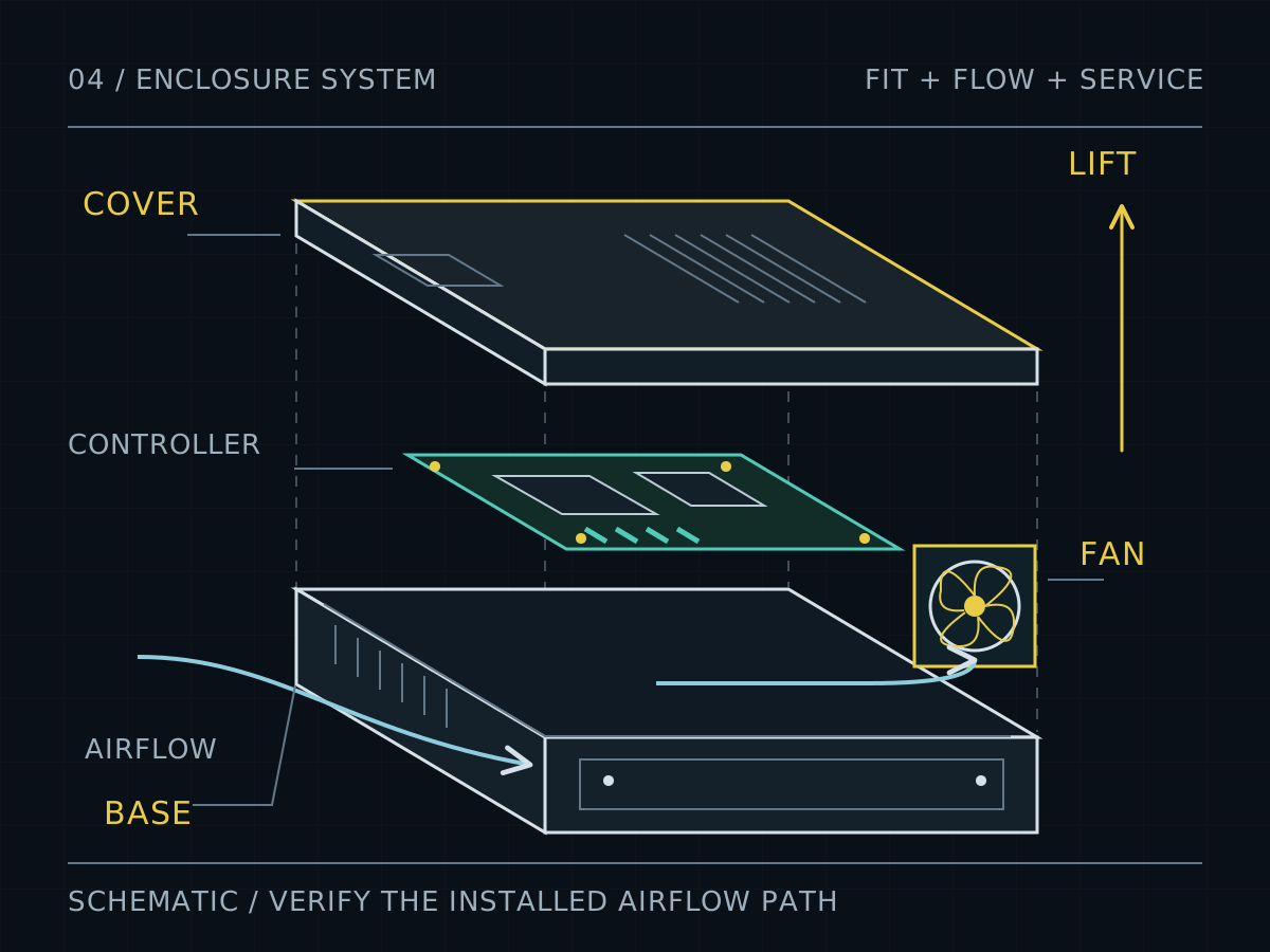
The Enclosure Is a System: Fit, Airflow, and Service Access
Start with what crosses the enclosure boundary.
A sheet metal enclosure connects several systems: the equipment inside it, its mounting structure, the surrounding air, the people servicing it, and the environment it must resist. Every connector cutout, removable cover, mounting rail, and vent is an interface between those systems. A dimensionally correct box can still obstruct a cable, trap heat, or require dismantling adjacent equipment to replace a fan.
Begin with an interface register. For each opening or attachment, identify the mating component, controlling dimensions, permitted variation, assembly direction, and person responsible for confirming the requirement. Include equipment that is absent from the mechanical model: connector backshells, cable loops, filters, washers, tools, and hands.
The result should distinguish the installed envelope from the service envelope. The first describes where the finished product sits. The second describes the space needed to operate, disconnect, remove, and replace it. Both belong in the design review. Our data center buildout article provides the broader sheet metal project context.
Locate deliberately. Clamp separately.
Decide which surfaces establish the position of the electronics and its external connections. A mounting tray might provide the primary reference plane, with selected features establishing the remaining directions. Refer the board supports and connector openings to a coherent reference system so that their relationship can be inspected.
A screw in a clearance hole does not establish a unique panel position before tightening. If alignment matters, specify a locating feature and its permitted clearance. One possible arrangement uses a round locator to establish position and a second locator in a directional slot to control rotation while allowing variation along their spacing. That is a design option requiring a tolerance review, not a universal enclosure rule.
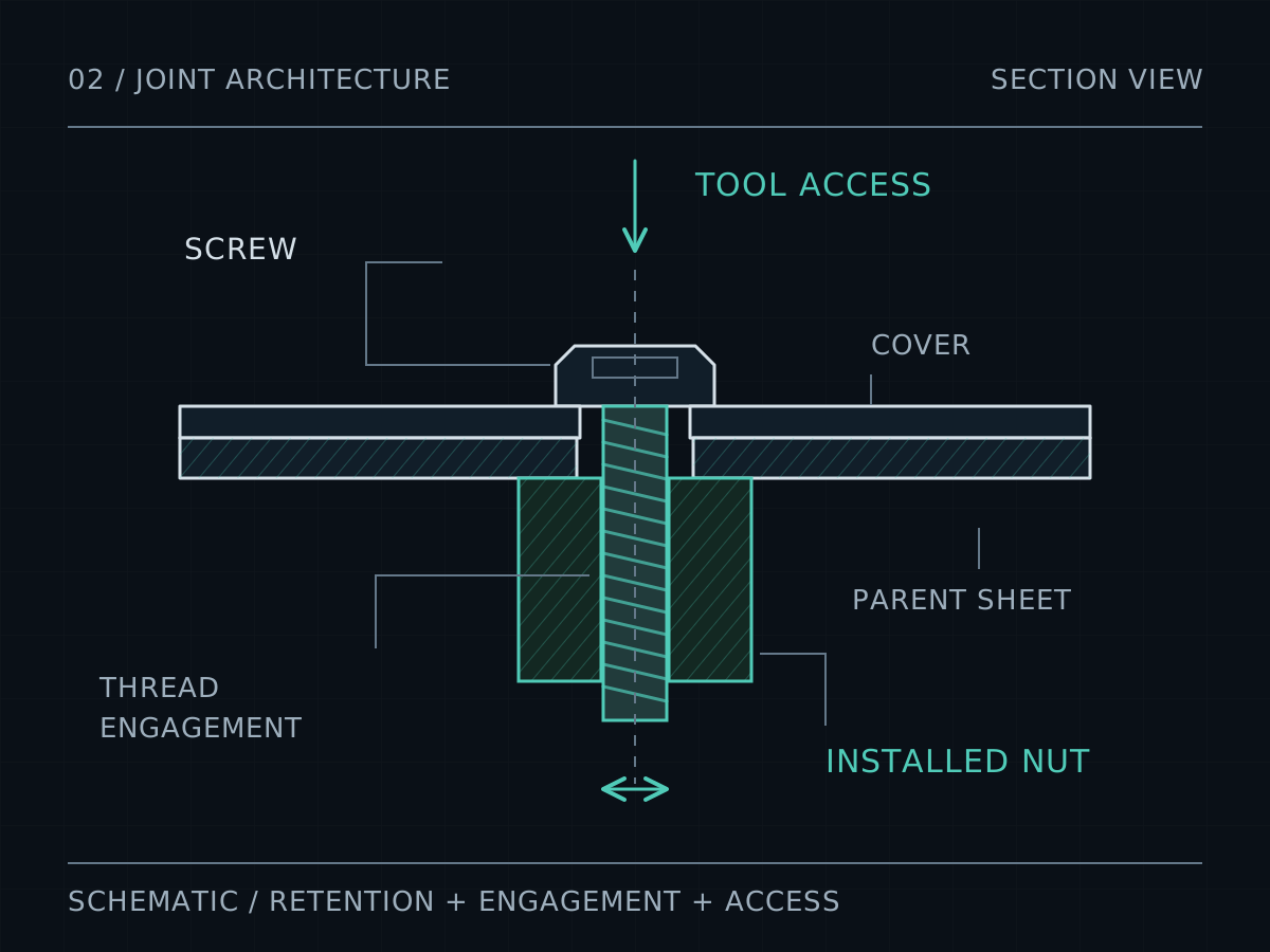
Give the remaining fasteners enough clearance to assemble without forcing the parts. Define their clamping and retention function separately. Avoid making every hole a tight locator: the resulting assembly may depend on several independently formed flanges arriving at exactly the same position.
On the drawing, show where the enclosure is supported and restrained during inspection. A flexible cover measured loose on a bench can behave differently once fastened. Use the technical drawing guide to communicate the controlling requirements.
Budget clearance in the finished condition.
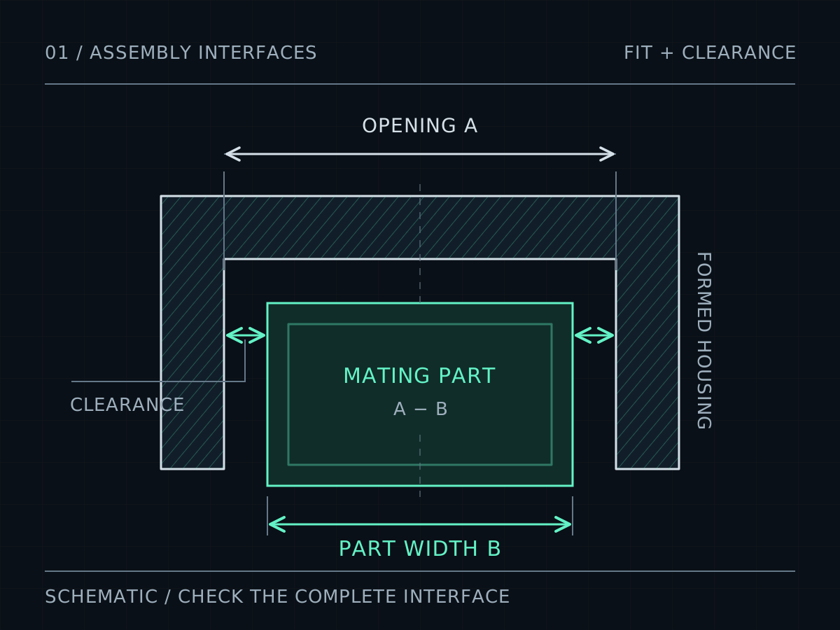
Finish is part of the fit calculation. If a bare gap lies between two coated faces, the finished gap is reduced by the film deposited on both faces. A sliding cover may involve four relevant surfaces: the two inside faces of the cover and the two outside faces of the body.
For a hypothetical width fit, let C be the bare cover opening, B the bare body width, and t a uniform coating thickness on each of those four faces. The remaining total width clearance is C − B − 4t. This simplified geometry illustrates what to count; it does not select a suitable clearance or establish a coating specification. Use the maximum specified deposits and adverse dimensional limits when checking minimum clearance. Explore the worked example in the assembly clearance calculator.
Identify threads, locating surfaces, and intended electrical contact areas that require a defined finish or masking treatment. Agree the treatment with the relevant designer and finisher. State whether acceptance dimensions apply before or after finishing, and inspect representative finished parts. See the powder coating guide for the finishing workflow.
Model the repair, including the tool.
A removable panel is useful only if it can be removed in the installed environment. Model its complete translation or swing, including the initial movement needed to release tabs. Check that neighboring cabinets, mounting brackets, and connected cables remain outside that swept space.
Next, model the service sequence. A driver needs an approach direction and working clearance. A captive screw still needs room to disengage. A connector may require finger access to its latch before it can move. A fan can fit through an opening yet remain trapped by its lead or a nearby bracket.
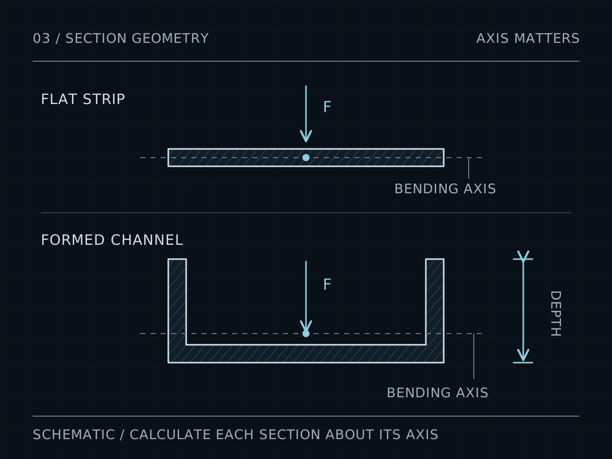
Use cable and connector manufacturers’ dimensions for bend space, strain relief, and disconnection travel. Decide whether a serviceable item leaves independently or as part of a tray. Review accessible edges along that movement and specify their required condition. Then confirm that the enclosure itself can be formed: a generous internal volume does not guarantee press-brake access. The box-height planning tool helps expose that separate constraint.
A vent pattern is only one part of the cooling path.
Geometric free area is the sum of unobstructed openings divided by the selected vent region. Define that region when reporting a percentage. The same percentage across two different panel areas produces different total openings, and equal open areas can still produce different flow resistance.
Inspect the whole air path: inlet, filter, guard, component arrangement, cable bundles, fan, and outlet. A decorative vent can be largely blocked by a mounting plate behind it. A direct shortcut from inlet to outlet can leave the components that need cooling outside the useful stream.
Installed airflow must account for system resistance. nVent’s cooling guide explains that grilles and internal equipment reduce airflow and calls for prototype verification at the intended heat load and ambient conditions. A fan’s unrestricted airflow figure therefore cannot establish enclosure cooling performance. Source: nVent cooling selection guidance.
Review the fan’s pressure–flow curve, not only its maximum airflow or maximum pressure. Noctua’s technical discussion demonstrates why performance through the curve can matter more than a single maximum value. Include the selected filter and its maintenance condition in validation. Source: Noctua fan performance explanation.
A controller enclosure review, before cutting metal.
Consider a hypothetical indoor controller with a folded base, removable cover, board tray, rear connectors, and replaceable fan. The first model contains every component without interference. The review nevertheless finds three problems.
Connector alignment: the board mounts reference the base, while the connector opening references a cover that floats in clearance holes. Move the opening to a panel with a defined relationship to the tray, or add an intentional locating scheme and verify the complete position stack.
Cover removal: rear tabs require the cover to slide backward, but connected cables occupy that space. Change the removal direction or put the connector interface on a fixed panel. Walk through the revised sequence with representative cables.
Fan replacement: the fan clears the cover but its fastening tool hits the tray. Change the fastener approach or create a removable fan carrier, then check its cable and extraction path.
These changes improve the design before a prototype exists. They do not prove its operating temperature, ingress protection, or shielding performance. Those remain separate verification tasks.
Keep geometry and performance claims separate.
IEC 60529 classifies degrees of enclosure protection under the IP Code. It is not a rating inferred from material thickness or the appearance of a closed CAD assembly. Source: IEC 60529 scope. Hammond also explicitly cautions that its NEMA-to-IP reference cannot be used in reverse to establish a NEMA Type. Source: Hammond protection-grade guidance.
Likewise, metal panels alone do not demonstrate electromagnetic compatibility. Seams, apertures, and cable interfaces affect shielding behavior, as nVent’s technical guidance explains. Source: nVent EMC guidance. A rack-shaped cabinet or familiar mounting-hole pattern also needs its actual interface dimensions, loading requirements, and applicable standards checked before any compliance claim.
Record the required performance, assembly configuration, verification method, and acceptance evidence. Revisit that record when a vent, gasket, connector, coating, or panel joint changes.
Release the enclosure with its interface evidence.
| Interface | Evidence to include |
|---|---|
| Mating parts | Reference system, critical dimensions, tolerance stack, and inspection condition. |
| Finished fit | Coating specification, masking map, and minimum finished clearance. |
| Assembly | Hardware identification, installation direction, and tool access. |
| Service | Removal sequence, swept envelopes, cable access, and replaceable items. |
| Cooling | Heat-load assumptions, complete air path, selected components, and validation plan. |
| Performance claims | Applicable requirements, evaluated configuration, and supporting results. |
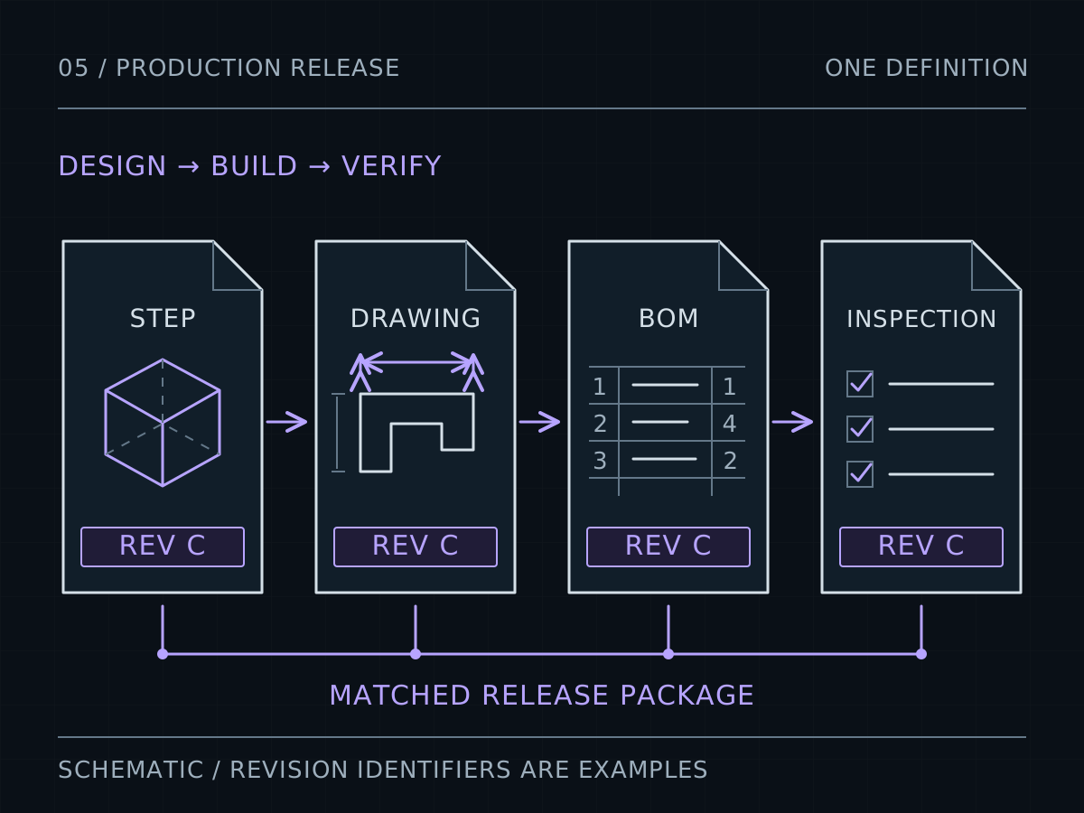
Issue the drawings, models, hardware list, and interface record as one consistent approved release, with each item’s revision identified. Give each unresolved item an owner. The fabrication package should make it clear which requirements are ready for production and which still require prototype evidence.
Sources & further reading.
Manufacturer data and technical references support the principles above. Worked scenarios are illustrative design studies. Confirm product-specific requirements against the selected material, hardware, and manufacturing route.
- nVent HOFFMAN: Cooling selection and system impedance
Manufacturer guidance on installed airflow, system resistance, and prototype thermal verification.
- Noctua: Anti-Stall Knobs technical explanation
Illustrates why pressure–flow behavior across the curve matters beyond maximum ratings.
- IEC 60529: Degrees of protection provided by enclosures
Official public scope of the IP Code standard; the complete requirements are in the standard.
- Hammond Manufacturing: Definition of protection grades IEC 60529
Manufacturer reference describing protection grades and the limitation of NEMA/IP cross-references.
- nVent HOFFMAN: Technical information on EMC
Manufacturer explanation of seams, apertures, and cable interfaces in enclosure shielding.
Connect this decision to the next.
Bring the interface into the quote.
Include your model, drawing, material, finish, and the dimensions that control the assembly.
Start a quote ↗