One part. Two different drawing jobs.
Use the formed drawing to accept the finished part. Use the flat drawing to communicate the developed blank.
This worked example uses a real three-bend bracket in Onshape and Xeon NC’s website entry for 0.100″ 5052-H32 aluminum. Its broad top flange, long side web, lower mounting ear, and small slotted flange show why one overall dimension is not enough.
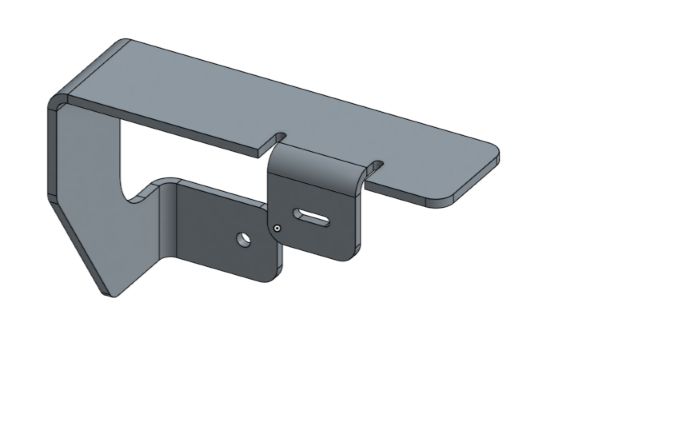
Instructional example, not a released production print. The screenshots show selected dimensions and development settings. A production drawing still needs the complete feature definition, functional tolerances, material and finish notes, revision control, and approval. The blank’s surrounding template is not an approved tolerance specification for this part.
Dimension surfaces you can actually check.
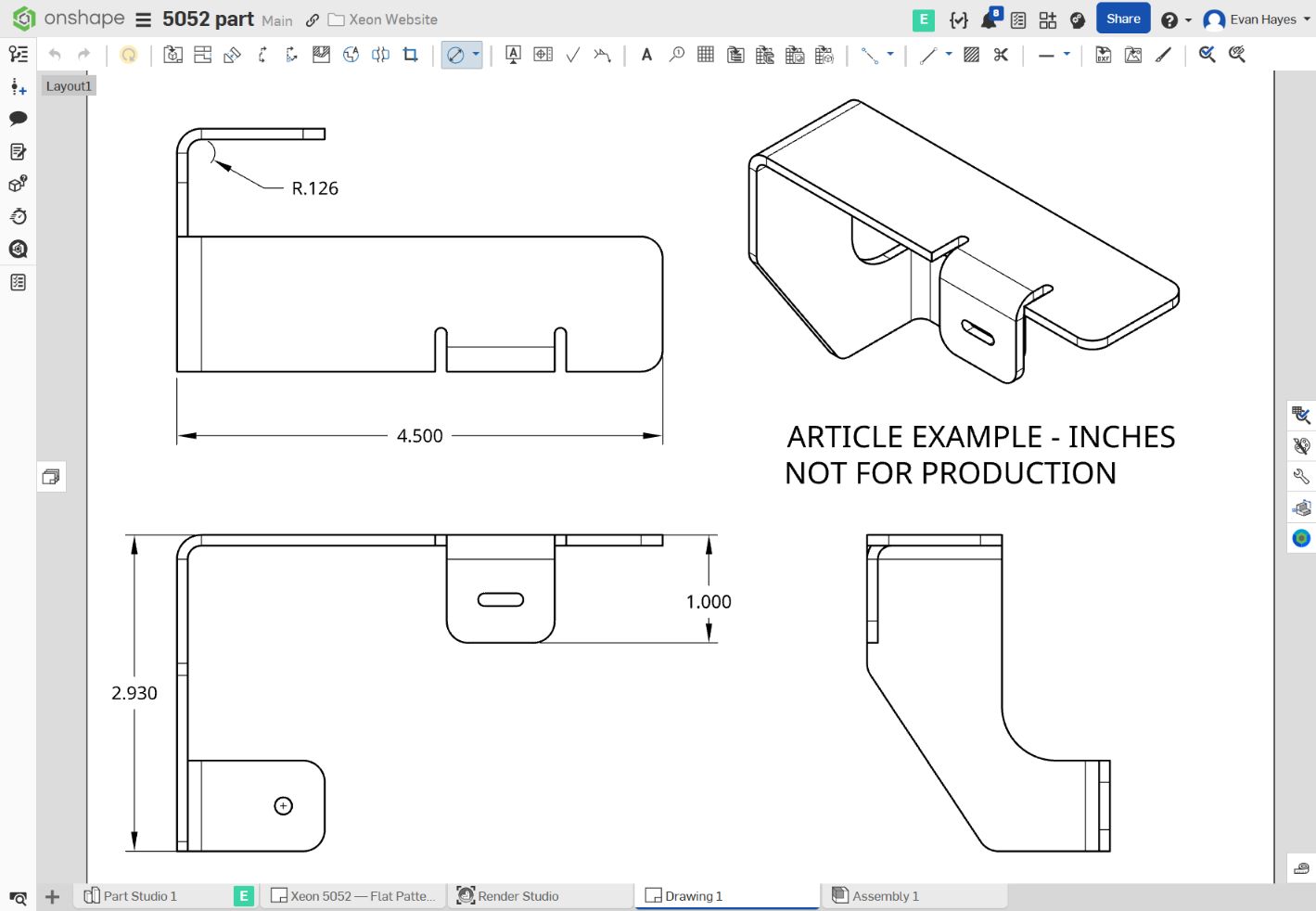
For this example, assume the broad top flange is the assembly’s seating face. Start the inspection scheme there. Confirm that assumption against the mating assembly before establishing formal datums.
| Drawing requirement | How to check it after bending |
|---|---|
| 4.500″ outside length | Measure between the two outside references shown in the upper-left view. Use calipers or a fixture appropriate to the required tolerance; avoid letting rounded corners change the contact points. |
| 2.930″ overall height | Reference the broad top face and measure to the lower edge. A surface plate and height gauge can be used with suitable supports, provided the part can sit without rocking or being forced into shape. |
| 1.000″ small flange height | Use the same top-face reference to check the slotted flange’s lower edge. Do not locate it through a chain of unrelated edges. |
| All three bend angles: 90° nominal | Check the adjacent straight faces with an angle instrument or fixture. A flange can meet an edge-height dimension and still have the wrong angle. |
| Mounting hole and slot | Check their sizes and positions relative to the functional references. A pin, optical system, CMM, or checking fixture may be more useful than measuring to a hole’s edge with calipers. |
Finish the location scheme.
A practical datum scheme could use the main seating face as A, a perpendicular locating face as B, and a suitable end face or locating feature as C. Choose these from how the bracket is constrained in its assembly, not from whichever edges are easiest to click.
Locate the round mounting hole in two directions and give its diameter. Give the slot’s width, overall length, orientation, and center location. If the slot provides adjustment, protect the direction that controls alignment and allow the intended travel in the other direction. Include the required formed offsets between these features; a perfect flat hole pattern can still miss its mating part after bending.
Use section or detail views where offsets, internal clearances, or short bend tangents are hard to see. Add appropriate position, orientation, or profile controls when ordinary size dimensions do not express the function. Thin sheet may need an agreed restrained inspection condition; never clamp a part into compliance without specifying that condition.
Call out the inside arc: R0.126″.
The radius dimension belongs on the inside cylindrical bend surface. Use the Onshape radial dimension tool on the inside arc in a view normal to the bend axis, or add a section/detail view that exposes it clearly. Keep the leader on that arc and leave room for the value.
For this example, the nominal inside radius is 0.126″ and the stock thickness is 0.100″. The ideal geometric outside radius is therefore 0.226″ = 0.126″ + 0.100″. The outside radius is useful for explanation or clearance calculations; it should not become a second independent acceptance requirement unless the design needs it.
All three bends currently use R0.126″. A common note can cover identical bends, with exceptions called out individually. Specify the radius tolerance required by the design and accepted by the shop; a three-decimal display alone does not establish that tolerance.
How to inspect the radius
A radius gauge gives a quick comparison when there is enough accessible arc. Use an optical profile measurement, CMM, or agreed contour method when the radius is critical. Inspect away from distorted reliefs and cut edges. Measuring two straight faces with calipers does not independently verify the bend radius.
Match the material row, not a generic K-factor.
The current Xeon bending data identifies the following setup for 0.100″ 5052-H32. The tool identities can be checked in the press-brake tooling library.
| Setting | This example |
|---|---|
| Material / thickness | 5052-H32 aluminum / 0.100″ (2.54 mm) |
| Lower tool | EV006 W20/30 R2 — 20 mm V opening |
| Upper tool | OW202/S R1/28 — 1 mm punch-tip radius |
| Developed-model inside radius | 0.126″ |
| K-factor | 0.40 |
| 90° bend deduction | 0.1912″ per bend, from the material row |
| Listed minimum flange | 0.496″ — verify the shop’s measurement convention and actual support |
The punch’s R1 marking is not the finished R0.126″. R1 is a 1 mm tool-tip radius; the air-bent part’s resulting radius depends on the die opening, material, thickness, and process. Likewise, the die’s R2 marking is not a 2 mm finished inside bend specification.
The 20 mm opening is about 7.87 times this stock thickness. It fits the tooling library’s screening guidance, but the small slotted flange still needs adequate die support. Check reliefs, slot-to-bend distance, tooling clearance, bend sequence, and tonnage. A 1.000″ outside flange height by itself does not prove every contact or collision check passes.
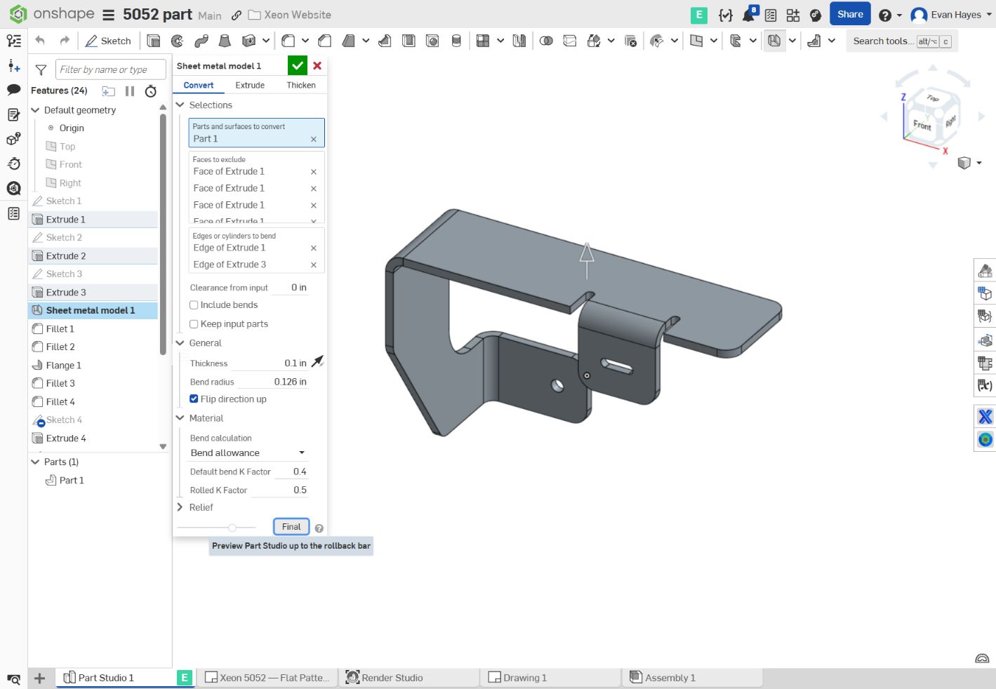
Check every bend, including overrides.
The original model had R0.125″ and K = 0.45 defaults, plus a Modify joint feature that repeated those values as overrides. Updating only the default would have left that joint inconsistent. The example now uses the model radius and K-factor for that joint, and its bend table reports all three bends at R0.126″ with approximately 0.261″ bend allowance.
Calculate the bend once. Do not compensate twice.
For an ordinary circular bend, let θ be the bend rotation from flat, in radians; R the inside radius; t the thickness; and K the neutral-axis factor. At a 90° bend, θ = π/2.
BA = θ × (R + Kt)
= π/2 × (0.126 + 0.40 × 0.100)
BA = 0.260752″ ≈ 0.2608″Outside setback = (R + t) × tan(θ/2)
BD = 2 × outside setback − BA
BD = 0.452 − 0.260752 = 0.191248″That calculated bend deduction rounds to Xeon’s listed 0.1912″. Onshape’s table displays the allowance as 0.261″ because of its display precision. Keep full precision in the model and round only for presentation.
| What you measured | Flat length for one bend |
|---|---|
| Straight lengths up to bend tangency | Lflat = straight 1 + straight 2 + BA |
| Outside leg lengths to the virtual sharp intersection | Lflat = outside leg 1 + outside leg 2 − BD |
For example, two hypothetical 2.000″ outside legs with this single 90° bend develop to 4.000 − 0.191248 = 3.808752″. Those are demonstration leg lengths, not dimensions taken from this bracket.
This bracket branches into separate flanges. Trace each development path through the bends it actually crosses. Do not subtract three bend deductions from the bounding-box length just because there are three bends. Let the validated sheet metal model develop the complete outline, then independently check representative paths.
When the CAD flat pattern already uses the approved allowance or deduction, do not apply the same compensation again in the cutting file or CAM system. Choose one owner for the production development.
Validate against an actual bend when needed.
Use a test coupon of the same grade, temper, thickness, tooling, and bend process. Measure the actual thickness, final angle, radius, and leg lengths. For a 90° coupon measured to outside virtual-sharp intersections, BD = outside leg 1 + outside leg 2 − known blank length. Compare that result with the table and adjust the controlled bend data with the shop if needed. Angle correction alone cannot recover an incorrectly developed blank length.
Show the blank and the bend instructions.
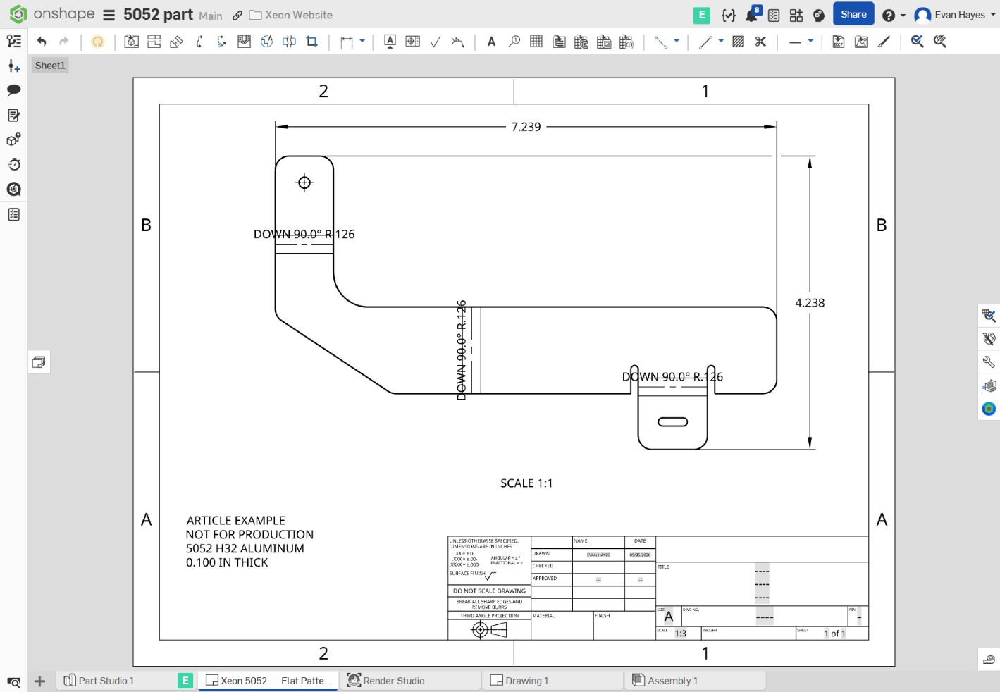
Create this view in Onshape by right-clicking the Part Studio’s flat pattern and choosing Create Drawing of Flat pattern of Part 1, or insert its flat pattern in an existing drawing. Use a readable scale and check every generated bend note against the formed model.
- Identify the viewing side. All three current notes say DOWN 90° R.126, relative to the shown flat view. UP/DOWN is not an absolute shop-floor direction.
- Locate bends unambiguously. Show bend centerlines and a bend table or clear notes. Add locations needed by the agreed manufacturing workflow; separate cutting geometry from bend-line geometry in the DXF as the shop requires.
- Define the rest of the blank. Overall length and width do not define the reliefs, corner radii, hole, or slot. Supply the controlled profile file and the remaining drawing requirements.
- Keep notes readable. Move crowded notes or use a bend table at release. Default placement on bend lines is useful while developing the drawing, but it can obscure a dense profile.
- State responsibility. If Xeon develops the production blank, mark the supplied flat pattern as reference under that agreed workflow. If it controls cutting, identify its revision and approved bend-development data.
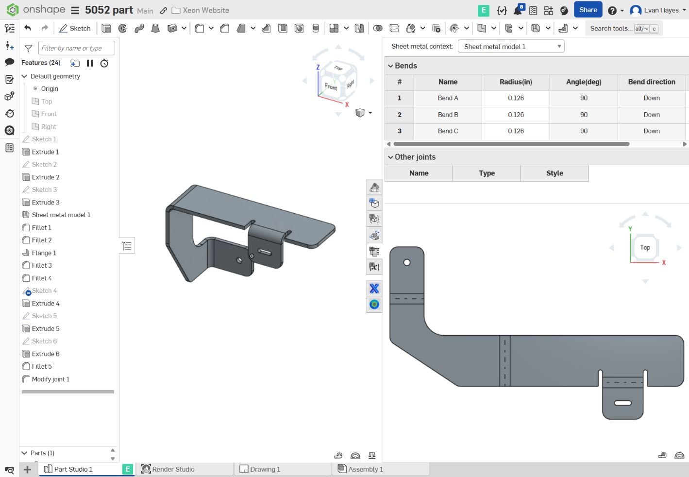
Release the folded model, drawing PDF, and any flat DXF together at the same revision. Confirm both the cutting geometry and the finished inspection requirements before manufacturing.
Define what the part must do.
A useful drawing tells the shop what to make, what must fit, and what to inspect.
Start with the assembly. Identify the mounting surfaces, bolt pattern, required clearances, and overall space available. These determine which dimensions need the most attention. A drawing should communicate the finished requirements clearly enough that the fabricator does not have to guess.
For your first sheet metal drawing, work in this order: material, views, dimensions, bends, tolerances, and manufacturing notes.
Specify the stock and the revision.
State the material grade and condition, nominal thickness, and finish. “Steel” or “aluminum” alone is incomplete. If you specify gauge, include the thickness and units too.
- Material: identify the alloy or grade and applicable temper or condition.
- Thickness: give the nominal stock thickness; identify a thickness tolerance if the application requires one.
- Drawing identity: part name, part number, revision, units, scale, and projection symbol.
- Acceptance: provide applicable general tolerances and individual tolerances for features that need them.
Use the drafting standard agreed for the project consistently. Do not mix dimensioning conventions or copy a tolerance block without checking whether it suits the part.
Show the formed part first.
Use front, top, and side views as needed to explain the shape. An isometric view helps the reader understand the part; a section or enlarged detail can clarify a small radius, countersink, or overlapping flange.
Dimension features where they are clearest. Show hole centers and centerlines where useful. Avoid forcing the reader to infer a feature from hidden edges or measure the page with a ruler.
Control the features that make it fit.
| Feature | What to communicate |
|---|---|
| Overall envelope | Finished length, width, and height. |
| Mating clearances | Inside opening or outside size, with unmistakable measurement endpoints. |
| Flanges | Length or height, and whether the dimension reaches a face, tangent, or theoretical sharp intersection. |
| Holes | Diameter, quantity, and center locations from useful references. |
| Slots | Width, overall length, orientation, and location. |
| Bends | Inside radius, finished angle, and bend direction where needed. |
| Cutouts & reliefs | Size and location where these are controlled design requirements. |
| Hardware | Exact fastener designation, location, and installation side. |
Inside and outside are different requirements.
For an ideal channel with parallel walls, a 100 mm inside opening and 2 mm stock produce a nominal 104 mm outside width. If the inside opening controls the fit, dimension that requirement. Do not give both sizes independent tight tolerances unless both are necessary and compatible with the stock thickness variation.
Reference dimensions provide information. They are not additional acceptance requirements. For the hypothetical channel above, identify the derived outside width as reference using the notation required by the drawing’s chosen drafting standard.
Locate holes from stable edges or mating surfaces. Common-reference dimensions help avoid an unnecessary chain of dependent measurements. Give each requirement one controlling dimension. See our formed-part dimensioning guide for datum choices and tolerance stacks.
Make the angle and radius clear.
Specify the inside bend radius and show which finished angle you mean. The angle between faces and the amount of rotation from flat are different conventions, especially away from 90 degrees. A drawing view should remove that ambiguity.
If bend notes say UP or DOWN, establish the viewing side. Check that the notes agree with the formed views. Discuss the radius, minimum flange length, bend relief, tool access, and achievable bend sequence with the fabricator.
Holes and cutouts close to a bend can distort during forming. Check our hole-to-bend guide and bend radius guide against the selected material and process. A generic rule of thumb is not a substitute for the shop’s requirements.
Agree who develops the blank.
A flat pattern describes the sheet before forming. Its developed length depends on bend allowance, bend deduction, or K-factor settings. Adding the finished flange dimensions does not give a reliable cutting length.
When supplying a production flat pattern, agree the development settings with the fabricator. When the shop develops the blank, identify your flat pattern as reference if that is the agreed workflow. Specify which files and dimensions control the finished part.
Keep the drawing PDF, folded model, and any cutting file on the same revision. Follow the shop’s cutting-file requirements for bend lines and annotations. Read STEP vs. DXF for fabrication for the role of each file.
Spend accuracy where it matters.
A tolerance defines the permitted variation. Select it from the part’s function and the fabricator’s capability. Tightening every dimension can add work without improving the assembly.
Dimensions across several bends accumulate position and angle variation. Holes on one flat face generally have fewer forming variables than holes on separate flanges. Review mounting patterns, inside clearances, and long flange tips carefully.
Specify coating, cosmetic faces, masking, weld requirements, and installed hardware where applicable. State whether critical fit dimensions apply before or after finishing. Use appropriate geometric controls when location, orientation, or form cannot be expressed adequately by size dimensions alone.
Be careful with blanket deburring notes. Self-clinching fastener holes have specific installation requirements. PEM warns against deburring these mounting holes because the removed material is needed for clinching. Follow the selected fastener’s hole size, sheet thickness, and edge-distance requirements.
Turn the model into a drawing.
- Set up the sheet metal model. Confirm thickness, inside radius, and bend-development parameters for the intended process.
- Create the drawing. Choose the appropriate template, units, sheet size, and projection convention.
- Place formed views. Add an isometric view and any sections or details needed to explain the geometry.
- Add the requirements. Dimension functional features, then add tolerances, material, finish, and hardware notes.
- Insert the flat pattern if needed. Onshape supports flat pattern views through the Insert dialog. Check bend lines, directions, and notes for clarity.
- Review and export. Update the drawing from the current model and confirm the PDF and supplied CAD files describe the same revision.
For the model handoff, see our Onshape STEP export guide.
Read it like the person making it.
- Material grade, thickness, finish, units, and revision are identified.
- The views fully explain the formed shape.
- Inside and outside measurement endpoints are unmistakable.
- Holes and slots are sized, counted, and located.
- Bend radii, angles, and direction are consistent.
- Important dimensions have achievable, inspectable tolerances.
- Hardware, finish, masking, and edge requirements are complete.
- Flat-pattern responsibility and controlling files are agreed.
- The drawing, model, and cutting files match the same revision.
Imagine receiving the drawing with no explanation. Every question you would need to ask is an opportunity to make it clearer.
Further reading.
Manufacturing limits depend on the supplier, material, and process. The external guidance below explains the principles; it does not establish Xeon NC’s acceptance tolerances.