Threads in Thin Sheet: Choose the Joint Before the Hole
Start with the joint's job
A threaded hole can look complete in CAD while the assembly remains unresolved. A service technician may be unable to hold the nut. A screw may bottom out before clamping the cover. An insert may survive installation but rotate during removal. These failures occur at the interface between the fastener, sheet, and assembly procedure.
Begin with four inputs: the load the joint must transfer, the surfaces it must clamp, the access available during manufacture, and the access available during service. Then specify whether the connection is permanent, occasionally opened, or routinely maintained. A cover retained against a gasket and a bracket carrying equipment require different evidence even when both use M4 screws.
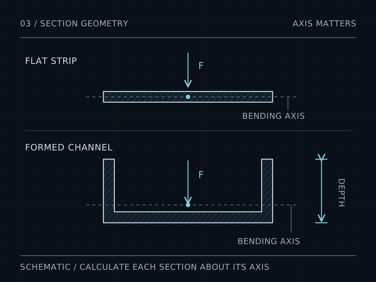
Keep thread strength, fastener retention, and panel strength separate in the review. A strong internal thread does not establish the sheet's resistance to local bending or pull-through. Likewise, an insert's resistance to rotation does not establish the clamping load that the complete joint can sustain.
Four ways to provide a reusable thread
| Joint approach | Useful starting condition | Decision that remains |
|---|---|---|
| Tap the parent sheet | Adequate effective engagement exists in the selected material. | Thread stripping, tightening limits, and expected service cycles. |
| Self-clinching nut | The panel suits the fastener and press tooling can reach both sides. | Hardness, thickness, hole condition, seating direction, and local clearance. |
| Blind rivet nut | A threaded attachment is needed where installation access is from one side. | Grip range, hole geometry, setting access, and space behind the sheet. |
| Through-bolt and separate nut | Both sides remain accessible during assembly and service. | Tool clearance, loose-part handling, bearing area, and retention method. |
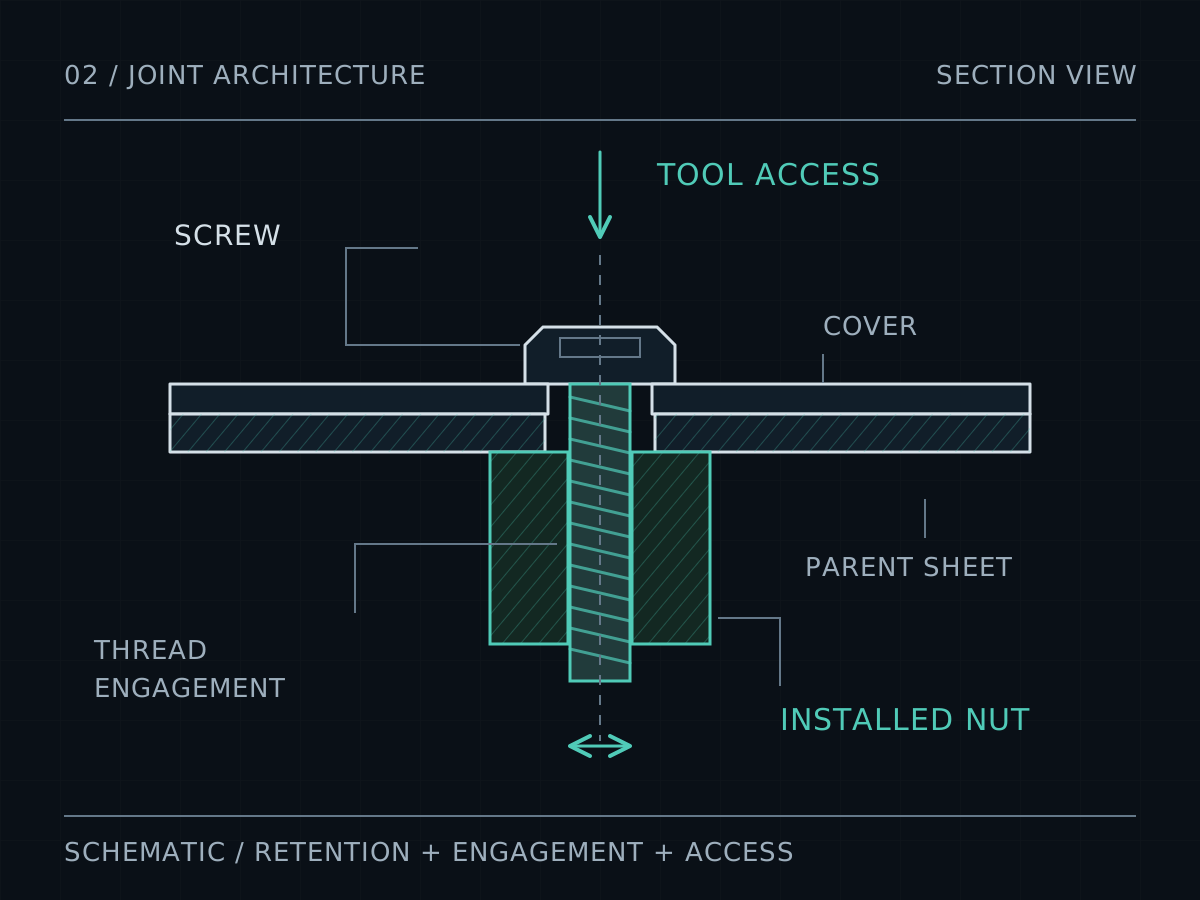
This table narrows the architecture; it does not rank strength. A through-bolt may simplify procurement while making field service slower. An installed nut may reduce assembly handling while adding a controlled manufacturing operation. Compare the complete procedure, including removal and replacement, before comparing the fastener price.
Böllhoff documents one-sided installation for its RIVNUT blind rivet nuts. That access advantage is valuable inside an enclosure, but it does not remove the need to check the installation tool's physical envelope.
A thread count is a screening calculation
For a flat sheet, dividing nominal thickness by pitch estimates how many pitches fit through the wall. It does not establish the number of fully effective threads or the joint's load capacity. Entry chamfers, incomplete thread forms, and the screw end can reduce useful engagement. Bossard's thread engagement guidance distinguishes effective engagement from nominal length and treats its calculation as a theoretical result requiring validation.
For example, 1.5 mm divided by a hypothetical 0.7 mm pitch is approximately 2.14 pitches. This arithmetic describes available geometry. It is not permission to assign a tightening torque or approve the joint for a load. Material strength, screw properties, thread tolerances, and the actual demand still matter; Bossard's engagement-length reference explicitly links the required engagement to the threaded component's material strength.
Use the Xeon tapping page to start a process discussion. Record the required thread and engagement on the drawing, and resolve the assembly requirements separately from whether a hole can be tapped.
Specify a fastener, then specify its hole
A self-clinching nut is retained when installation displaces suitable panel material into the fastener's retention geometry. PennEngineering's nut-family information lists different allowable sheet hardnesses for different fastener types. The word stainless, by itself, does not define a compatible fastener-and-panel combination.
Select the complete part number, including the applicable shank or sheet-thickness code. Then transfer its mounting-hole size and tolerance, minimum sheet thickness, hardness restriction, and edge-distance requirement into the design review. Do not substitute a universal hole allowance or a generic thickness multiple for product data. The hardware size chart helps organize that selection; the chosen manufacturer's specification must govern the exact item.
Hole condition belongs in this review. PennEngineering's installation instructions caution against deburring clinching holes because removing surrounding material can interfere with retention. Reconcile any blanket edge-break note with the hardware-hole requirement before release. If the cutting process leaves an unsuitable hole condition, agree a qualified preparation method with the fabricator.
Model the installation tool and the repair
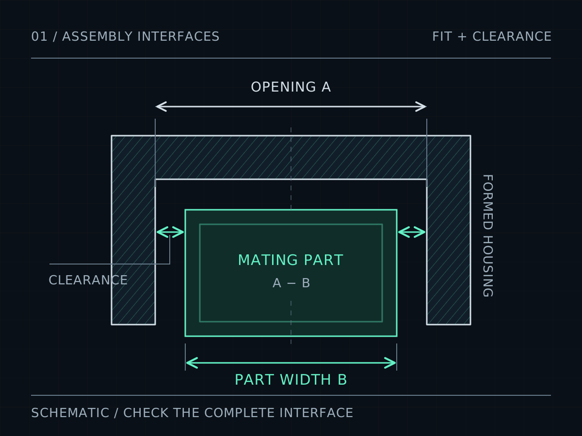
Place a simplified punch, anvil, setting tool, socket, or wrench envelope in the assembly model. Check approach direction, seating contact, withdrawal, and adjacent flanges. A nut that fits the finished enclosure may be inaccessible to its installation equipment after the last bend. That is a sequencing problem the drawing should resolve.
For a blind rivet nut, distinguish the material captured during setting from the removable part later attached by the screw. Böllhoff's RIVNUT catalog defines grip range by the captured material thickness, and separately identifies blind-side projection and bulge diameter. Reserve that volume around wiring, insulation, and adjacent walls. A cover added after setting is not part of the installed grip stack.
For repeated service, define the expected removal cycles and an assembly torque window appropriate to the selected joint. Review insert rotation, thread damage, screw length, and the recovery procedure if a fastener fails. Round, knurled, and hexagonal rivet-nut bodies are different options; choose the hole and anti-rotation arrangement together. Do not interpret torque-out test data as a recommended screw-tightening torque.
Finishing order depends on the interface
A single instruction to install all hardware before finishing is too broad. So is an instruction to install everything afterward. The correct sequence depends on panel material, hardware material, coating chemistry, coating thickness, and the surfaces needed for installation.
PennEngineering's surface-finishing technical sheet explains that thick additive coatings can obstruct clinching and identifies masking the hole and surrounding installation area as one possible way to finish first. Its installation cautions also address steel or stainless fasteners in aluminum before anodizing or finishing. These are reasons to agree a route for the actual material combination.
Write down which threads, seating faces, and contact areas must remain clear. Define any permissible coating damage or touch-up procedure with the finisher. If electrical bonding matters, give that interface its own requirement. Use the powder-coating guide alongside the hardware drawing so the cosmetic finish and the mechanical joint are reviewed together.
Worked decision: a removable electronics cover
Hypothetical design exercise: an enclosure uses 1.5 mm aluminum sheet, four M4 screws, and a removable cover expected to be opened monthly. Once electronics are installed, the technician can reach only the screw-head side. No load rating or approved hardware selection is implied.
The access requirement removes a loose nut from the preferred service procedure. The nominal pitch calculation above flags limited parent-sheet engagement, so direct tapping requires more justification. The designer first evaluates a self-clinching nut installed while the panel is accessible, checking the exact fastener against sheet thickness and hardness. Forming and finishing order must preserve access and the required hole condition.
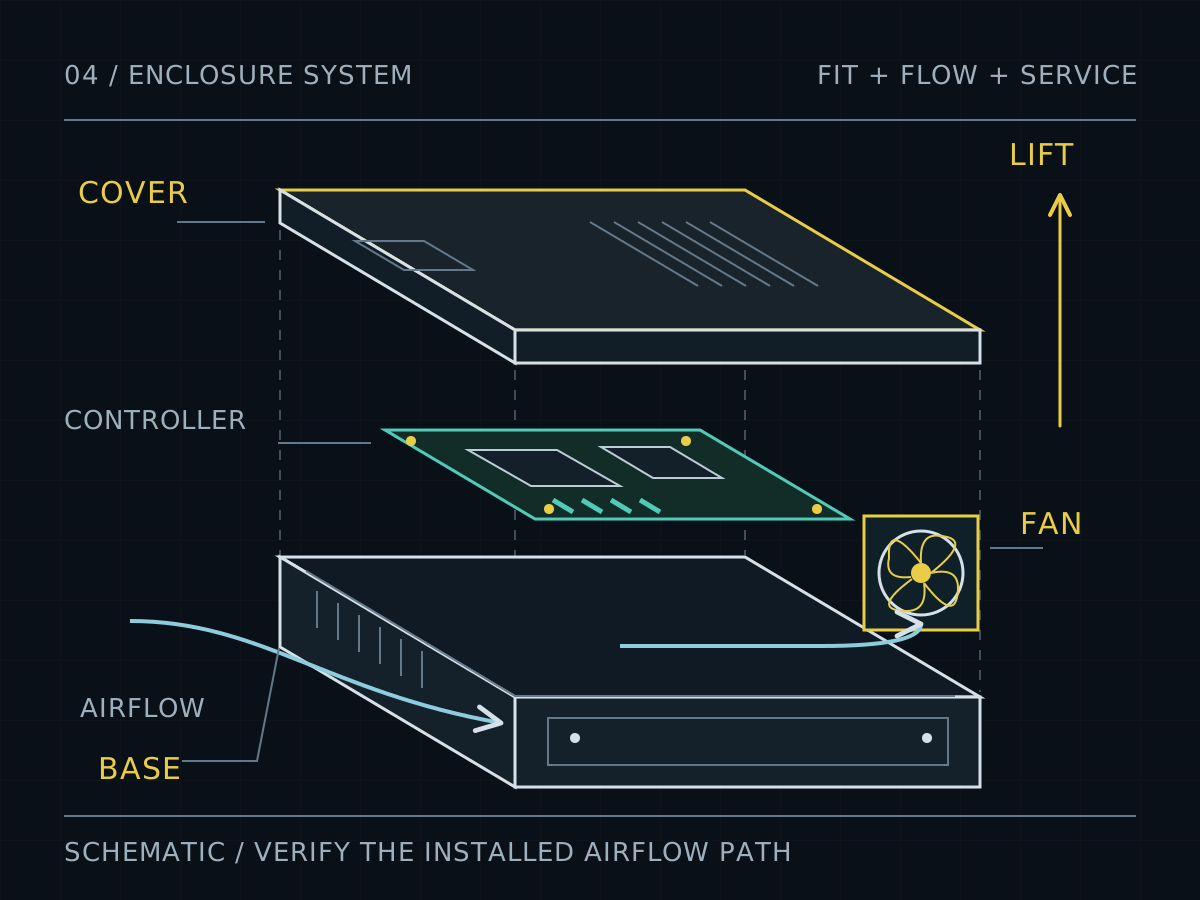
If the panel reaches hardware installation only after the enclosure is closed, a blind rivet nut becomes a candidate. The designer checks the actual grip stack, setting-tool reach, rear clearance, and head projection beneath the cover. A clearance change may be necessary before the joint can close as intended.
The output is a documented candidate joint and a verification plan: installation trials in representative material, seating checks, an agreed tightening procedure, and service-cycle evaluation. The hole is released after that selection, rather than becoming an assumption that every later operation must accommodate.
Release the connection as a complete instruction
- Joint function: loads, clamped surfaces, service access, and expected removal cycles.
- Exact hardware: manufacturer, part number, thread, material, finish, and approved substitutions.
- Panel and hole: thickness range, material condition, applicable hardness, mounting-hole geometry and tolerance, and local clearance.
- Installation: direction, tool access, support, sequence relative to forming, and acceptance criteria.
- Finish and service: masking, interface condition, screw length, tightening procedure, and replacement approach.
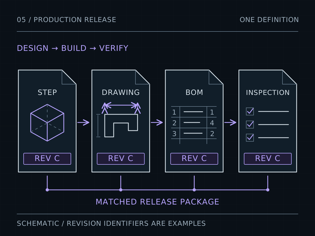
Bring the model, drawing, and hardware specification together when reviewing hardware insertion. They should describe one connection that can be made, inspected, assembled, and serviced without reconstructing the designer's intent.
Sources & further reading.
Manufacturer data and technical references support the principles above. Worked scenarios are illustrative design studies. Confirm product-specific requirements against the selected material, hardware, and manufacturing route.
- PennEngineering: Self-clinching nut families
Retention mechanism and product-family-specific panel hardness restrictions.
- PennEngineering: Installation do's and don'ts
Mounting-hole condition, pressing practice, and material/finishing cautions.
- PennEngineering: Surface finishing sheet metal assemblies
Coating thickness, masking, and process-order considerations.
- Böllhoff: RIVNUT blind rivet nuts and studs
One-sided installation and available fastener-body configurations.
- Böllhoff: RIVNUT technical catalog
Grip-range definition, installation geometry, and product-specific setting information.
- Bossard: Length of engaged thread
Dependence of required engagement on threaded-component material strength.
- Bossard: Thread engagement length calculator
Effective engagement, run-in/run-out effects, and limits of theoretical calculations.
Connect this decision to the next.
Bring the interface into the quote.
Include your model, drawing, material, finish, and the dimensions that control the assembly.
Start a quote ↗