A tolerance is an acceptance interval.
A CAD model gives a part its nominal shape. The drawing defines how far the manufactured part may depart from that shape and still work.
Consider a dimension of 50.00 ±0.10 mm. The permitted size runs from 49.90 to 50.10 mm. The total tolerance width is 0.20 mm. The tolerance is the requirement; it is not a prediction that the machine will produce every part at the center of that interval.
In measurement, accuracy concerns agreement with the value being measured. Precision concerns agreement among results under stated conditions; repeatability addresses repeated measurements under the same conditions. A process can repeat the same offset very consistently and still fail the drawing. NIST’s terminology guidance distinguishes accuracy, precision, repeatability and reproducibility.
A size tolerance also does not describe every geometric requirement. A hole can have an acceptable diameter and still be in the wrong place. A panel can have the correct width and still be bowed. Where function requires it, the drawing must address location, orientation, form or profile as well as size. Our GD&T guide introduces those controls.
Sheet metal carries several kinds of variation.
A sheet-metal part starts with stock whose thickness and condition already vary within the material specification. Cutting creates a two-dimensional outline. Bending then changes the relationship between surfaces. Welding, hardware insertion and finishing may add further changes.
Features on one flat surface
Two holes cut into the same flat panel can share the same cutting setup. Their spacing does not inherently include a bend-angle contribution. Cut-edge quality, kerf compensation, thermal effects and distortion still matter; the laser’s positioning specification alone is not a finished-part tolerance.
Features across a bend
A hole on an upright flange must satisfy the flat layout and the formed geometry. Its final location depends on the bend position, radius, angle and the point from which it is measured. Material thickness, tooling, backgauge contact and springback affect that result. A Penn State research publication on aluminum V-bending examines how material and forming parameters affect springback and its variability.
Stock thickness and surface condition
Cutting a sheet outline does not machine the entire sheet to a controlled thickness. A slot-and-tab fit therefore combines a cut slot dimension with the actual thickness of the mating sheet. Likewise, dimensional width and free-state flatness need separate attention. See our coil-leveling article for the difference between initial flatness and stability after cutting.
Features near the bend zone
A hole placed too close to a bend can distort as nearby material stretches. A tight hole diameter callout does not prevent that deformation. Move the feature, add suitable relief, or discuss a secondary operation after forming. Our hole-to-bend distance guide explains how to evaluate feature placement.
A precise flat pattern is the starting condition. The formed part needs its own acceptance criteria.
Specify the finished part and supply the folded model. Let the fabricator review bend allowance and tooling compatibility before treating an exported flat pattern as production-ready. If both flat and formed drawings are supplied, establish which dimensions control acceptance so conflicting requirements do not reach the shop floor.
A small angle can move a feature a long way.
The farther a mounting point sits from a bend, the more lateral movement a given angular error creates.
For a flange nominally perpendicular to a fixed base, a point at lever arm H moves laterally by H sin(θ) when the flange rotates by θ. At H = 100 mm and θ = 0.5°, the angle contribution alone is about 0.873 mm in either direction. A ±0.5° angle callout and a ±0.10 mm lateral location callout can therefore demand very different levels of control.
δ = H sin(θ) / bound = ±(δ + T)
A rigid flange rotating about a fixed idealized pivot. H is the actual lever arm to the evaluated point, not automatically a drawing’s outside flange dimension. The angle spread is magnified 10×; the drawn flange length stays fixed for readability. Numerical results use the real input values.
The second output adds a separate lateral allowance to the angular contribution as a conservative worst-case bound. Use it to understand sensitivity. Real formed-part analysis must account for the defined datums, bend radius, thickness, actual lever arms, measurement directions and correlated effects. Do not count the same error twice.
Three useful design responses are to shorten the lever arm, allow adjustment where the assembly permits it, or establish a process that controls the critical feature after forming. Simply tightening the laser-cut hole location will not remove movement caused by a varying flange angle.
CNC machining creates surfaces from a setup.
Machining removes material to establish faces, bores, pockets and other features. When related features can be finished from the same stable setup, the machinist can control their relationship directly through the toolpath and work coordinate system.
That offers a different route to precision than cutting a flat sheet and rotating part of it through a bend. A bore can be finished to size, a mounting face can be machined, and a critical relationship can sometimes be completed in one setup. The opportunity depends on tool access, part stiffness and the required geometry.
Machining still has limits. Tool deflection, wear, workholding distortion, heat and movement when clamps are released can affect the result. Reorienting a part introduces another setup relationship. A thin machined wall may be more difficult to hold than a short, well-supported feature. “CNC” is a process family, not a blanket guarantee for every dimension.
Research archived at Purdue University on machine-tool accuracy models geometric and thermally induced errors at the cutting tool and investigates compensation. It provides a physical explanation for why machine motion and thermal state matter to the finished workpiece.
Keep tight tolerances on the surfaces and features that locate, seal or carry load. Allow more freedom where it has no functional consequence. The applicable quote and drawing establish the requirements for the actual part.
Sheet metal can also receive secondary machining. A formed bracket may have a critical hole drilled or reamed afterward, provided it can be supported and located appropriately. That hybrid route should be planned and quoted, because it adds handling, setup and inspection.
A printed dimension belongs to the whole build process.
3D printing builds geometry layer by layer. Its dimensional behavior depends on the technology, material, orientation, machine settings and the condition in which the finished part is measured. NIST research on tolerance transfer identifies build direction, process variation, design intent and datum references as factors in additive process planning.
Layer height is not dimensional tolerance. A 0.10 mm layer setting does not mean every feature will be within ±0.10 mm. Resolution describes aspects of how geometry is represented or formed; the completed part still reflects material behavior and processing. In laser powder-bed fusion specifically, NIST’s Powder Bed Layer Geometry study examines machine errors that can affect both layer thickness and part geometry.
| Printing route | Dimensional questions to resolve |
|---|---|
| FDM / material extrusion | Which faces carry layer steps or supports? How do cooling, warping and support removal affect the fit? |
| SLA / resin printing | Is acceptance measured after washing, support removal and the required post-cure? How is shrinkage compensated? |
| SLS / MJF polymer powder bed | How do build orientation, thermal behavior, cooling and surface finishing affect this material and feature size? |
| Metal additive manufacturing | Which interfaces require heat treatment, support removal or finish machining before inspection? |
Post-processing belongs in the specification. NIST’s Additive Manufacturing Part Qualification project identifies heat treatment, machining and chemical or mechanical polishing as treatments that can affect part characterization, including dimensional measurements. An as-printed prototype and a finished production part should not be compared without recording their processing condition.
Printed holes, thin walls and mating surfaces deserve application-specific trials. A successful fit in one orientation and material does not establish the same result in another. If a bore or locating face requires machining after printing, identify it on the drawing instead of assuming the printed surface will satisfy the finished requirement.
Compare the feature, not just the process name.
| Question | Sheet metal | CNC machining | 3D printing |
|---|---|---|---|
| How is geometry established? | Stock thickness, cut profile and forming operations. | Material removal relative to the setup and toolpath. | Layerwise build plus required post-processing. |
| Where do errors accumulate? | Across bends, changing datums, hardware, welds and finishes. | Across setups, deflecting features, tooling and unclamping. | Across orientation, scale, material behavior and finishing. |
| A useful precision strategy | Keep locating features on a common stable face; qualify cross-bend relationships. | Finish related critical features from a suitable common setup. | Validate the chosen material and orientation; finish-machine selected interfaces if needed. |
| What should the drawing state? | Formed geometry, bend convention, functional datums and free or restrained inspection state. | Critical sizes, datum scheme, geometric controls and finish condition. | Material/process, critical features, post-processing and inspection condition. |
There is no defensible universal ranking in which every machined dimension is tighter than every sheet-metal or printed dimension. A same-surface laser-cut hole pattern and a cross-bend enclosure width are different problems. So are a small resin feature and a large polymer powder-bed housing.
How to read Xeon’s published starting points
| Service-page reference | Published value | What it applies to |
|---|---|---|
| CNC press brake | Standard angle: ±0.5° | Bend angle, subject to material and flange conditions. It is not a linear hole-position tolerance. |
| CNC machining | Standard: ±0.005 in. Selected tight features: ±0.001 in. | The service page distinguishes general machining from critical features requiring tighter control. |
| 3D printing | Standard XY accuracy: ±0.2 mm | Geometry and the selected additive process affect applicability. This is not a universal XYZ guarantee. |
These summarize the linked Xeon service pages as reviewed September 12, 2026. They describe different quantities and should not be compared as interchangeable capability limits. Confirm the actual material, feature, finish, quantity and acceptance requirements during quoting. ±0.005 in. equals ±0.127 mm; ±0.001 in. equals ±0.0254 mm.
General tolerances need to be explicitly adopted on the drawing or agreed in the quote. MIT’s Manufacturing Processes and Systems lecture notes distinguish design-specified limits from variation produced by the process. A process capability estimate and a drawing requirement therefore answer different questions. Copying a tolerance block from another manufacturing process can create unintended requirements.
Spend the tolerance budget where the parts meet.
Start with the interfaces. Which face seats against the assembly? Which hole locates it? Which gap allows installation? Those questions should guide the datum scheme and the critical dimensions.
A datum reference gives inspection and manufacturing a common basis for locating the part. Dimensioning related features from functional references can avoid unnecessary chains through intermediate features. It does not eliminate bend variation or guarantee that every feature is physically independent.
A clearance example
Suppose a receiving opening is 20.50 ±0.15 mm and the mating part is 20.00 ±0.10 mm. The nominal clearance is 0.50 mm. At worst-case limits, the minimum is 20.35 − 20.10 = 0.25 mm; the maximum is 20.65 − 19.90 = 0.75 mm. The two nominal sizes alone do not describe the fit.
That simple subtraction assumes the evaluated surfaces are aligned and ignores form, position, coating and thermal effects. Add the relevant contributors for the real assembly. If both opposing faces receive coating, account for both surfaces; state whether dimensions apply before or after finishing.
Slots and clearance holes can accommodate variation where adjustment is acceptable. Locating pins, machined interfaces or a controlled fastening sequence can be appropriate where position must be repeatable. Choose the arrangement from the function instead of making every hole equally tight.
Worst-case stack analysis combines limiting deviations. Statistical methods need evidence about the contributing processes and their relationships. An assumed statistical cancellation is not a substitute for checking whether the assembly will meet its requirement.
Make the inspection condition part of the requirement.
- Identify the delivered condition. State the material, thickness or stock specification, finish and required processing. For sheet metal, identify the formed configuration; for printing, identify the post-processing condition.
- Choose functional references. Use stable locating faces or features. Define datums and orientation requirements where the part’s function needs them.
- Separate the dimensions. Distinguish cut sizes, hole locations, flange lengths, bend angles, flatness and hardware positions. A general tolerance cannot explain which state or feature you intended.
- Highlight critical interfaces. Call out mating holes, sealing faces, bearing fits and other genuinely necessary controls. Avoid redundant dimensions that impose conflicting acceptance limits.
- Agree on measurement and evidence. Define the inspection support, sampling or first-article requirements, and any needed results report before production.
A thin flange can move when caliper jaws squeeze it. Burrs, coatings, rough surfaces and temperature can also affect a reading. Choose an instrument and setup suitable for the feature: calipers for appropriate accessible sizes, micrometers for suitable thickness measurements, and surface-plate, height-gauge, optical or coordinate-measuring methods where the requirement warrants them.
An instrument’s display resolution is not proof that the entire measurement is accurate enough. Alignment, contact force, calibration and measurement uncertainty need to suit the tolerance. A hole’s diameter measurement alone cannot establish its position relative to the datum system.
For flexible parts, say whether inspection occurs freely supported or in a defined restraint that represents assembly. Clamping a panel flat can change the result. Specify that condition deliberately rather than leaving the inspector to infer it.
A concise drawing-review request
Part / revision: [identifier]
Material / process: [alloy, temper, thickness or print material]
Delivered condition: [formed, finished, cured, machined, etc.]
Functional references: [datum faces / locating features]
Critical requirements: [size, position, angle, form / profile]
Inspection condition: [free support or defined restraint]
Finish allowance: [requirements before / after finishing]
Evidence: [first article, sampling and reporting]
Mating condition: [relevant assembly drawing or fit description]
Can I use the same tolerance block for all three processes?
Only after confirming that every requirement is appropriate for the actual material, geometry, process and inspection method. A copied block can impose unnecessary cost or miss an important formed or finished condition.
Does a tighter cut tolerance fix a cross-bend alignment problem?
It may reduce one contributor. It does not remove bend-angle variation, material effects or the movement of the reference features. Evaluate the complete relationship after forming.
Is a 0.1 mm print layer the same as ±0.1 mm accuracy?
No. Layer height and completed-part dimensional accuracy are different quantities. Qualify the final part in the required orientation, material and post-processing condition.
Define the fit. Then choose the control.
A useful tolerance explains what the part must do, where it is measured and which variation the assembly can accept. That gives the manufacturer a concrete requirement to plan, quote and verify.
Review a drawing or critical fit with Xeon →Sources and further reading.
University teaching materials and research publications, together with work from the National Institute of Standards and Technology (NIST), support the technical discussion. References reviewed September 12, 2026. The mathematical examples are original, idealized engineering illustrations; research results are not used as Xeon process-capability guarantees.
- MIT — Manufacturing Processes and Systems, Lecture 1 (2018), slide 45: design specification limits and process variation.
- Penn State — Springback Reduction of Aluminum Sheet in V-Bending Dies (2014), I. A. Choudhury and V. Ghomi: material and process influences on springback.
- Purdue University — A General Methodology for Machine Tool Accuracy Enhancement, M. Alkan Donmez: geometric and thermal machine errors and compensation.
- NIST — Technical Note 1297, Appendix D.1: Terminology: accuracy, precision, repeatability and reproducibility.
- NIST — Challenges in Tolerance Transfer for Additive Manufacturing (2016), G. Ameta, S. Moylan and P. Witherell: build direction, process variation and datum references.
- NIST — Powder Bed Layer Geometry (2016), M. McGlauflin and S. Moylan: machine errors affecting layers and part geometry in laser powder-bed fusion.
- NIST — Additive Manufacturing Part Qualification: dimensional characterization and the effects of post-processing.
Continue with dimensioning formed sheet-metal parts, precision-machined tolerancing, 3D-printing design, or sheet-metal technical drawings.
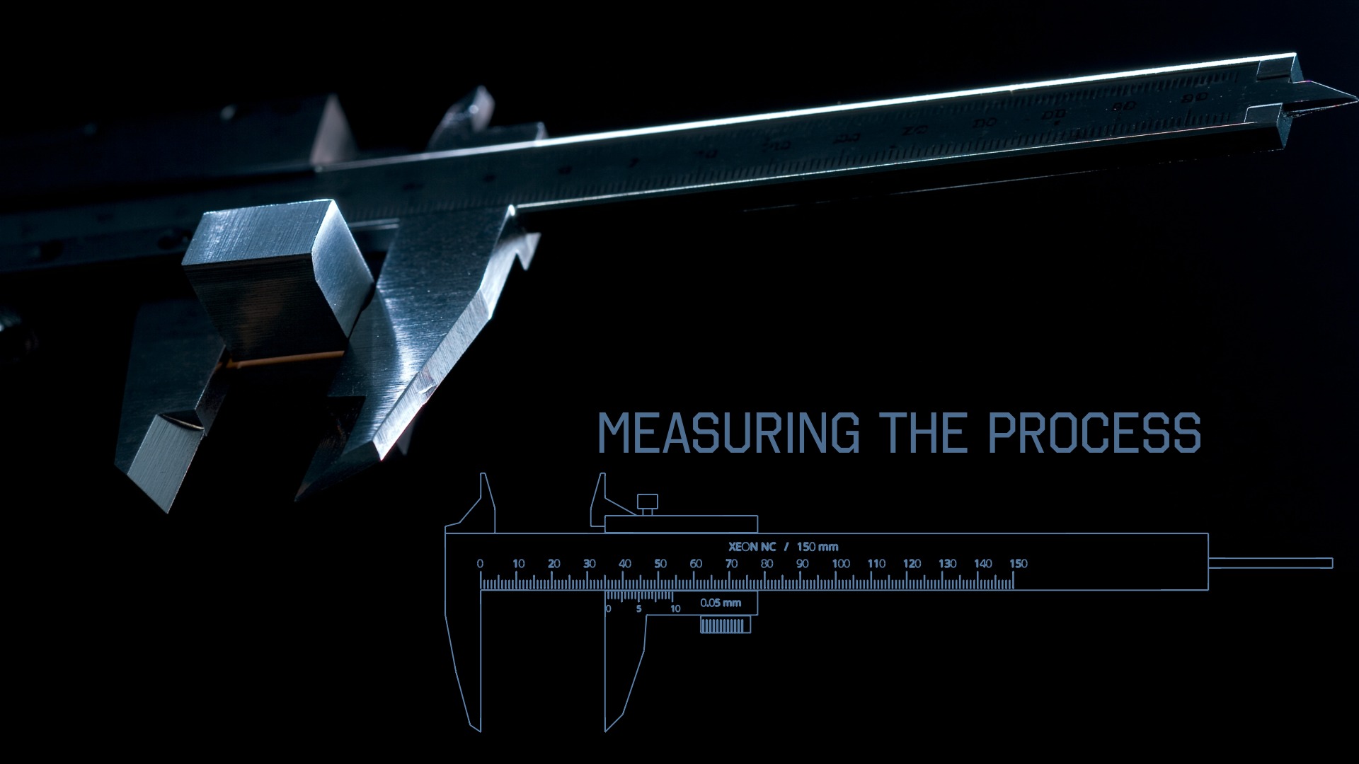
Cover image supplied by Xeon NC and used as an editorial illustration of dimensional inspection. No instrument reading or inspection result is inferred from the image.