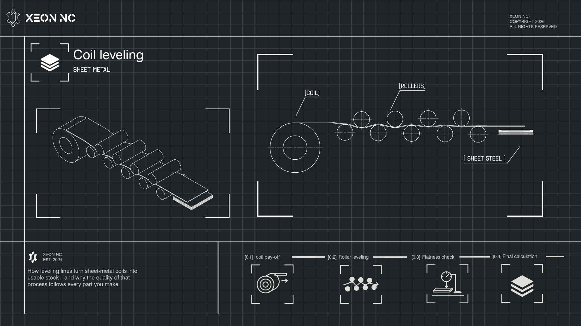
The first operation happened before the sheet arrived.
A laser-cut part inherits more than an alloy and a thickness. It inherits the shape and stress history of the sheet it came from.
Coiling makes long lengths of metal practical to handle and transport. Unwinding the coil does not automatically produce a flat blank. The strip can retain longitudinal curvature, carry uneven shape across its width, and contain residual stresses from earlier processing. A leveling line prepares that strip for the next operation.
Two conditions need separate attention: visible flatness, measured on the unloaded sheet, and stability after material is removed. A balanced residual-stress pattern can exist in a sheet that appears flat. Cutting changes that balance; a narrow rail or open frame may move as it separates from the surrounding stock. Bradbury describes this downstream stress problem.
| Shape condition | What the operator sees | What must be understood |
|---|---|---|
| Coil set | Curvature along the rolling direction. | The strip retains a tendency to curl after unwinding. |
| Crossbow | Curvature across the strip width. | Widthwise shape requires attention beyond longitudinal curl. |
| Edge wave | Ripples along one or both edges. | The affected edge is effectively longer than the adjacent tighter material. |
| Center buckle | A wavy center between tighter edges. | The center is effectively longer than the surrounding edge regions. |
Shape correction references: Butech Bliss roller and stretch levelers and Bradbury’s leveling process.
A controlled sequence turns coil into usable stock.
A cut-to-length line is a system of coil handling, feeding, shape correction, length control and stacking equipment. Equipment order varies: a line may include a flattener ahead of a precision leveler, an accumulator, a stretcher, or a temper mill. The simplified model below isolates the part of the system that changes curvature.
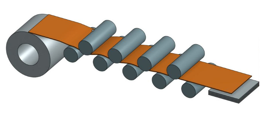
- Load, support and unwind.A payoff reel supports the coil while entry equipment controls the leading end and feeds the strip into the line. Handling equipment must match coil weight, width and inside diameter.
- Remove the gross coil curvature.Entry flattening can make the strip manageable. That initial straightening step does not, by itself, establish the required final flatness or cutting stability.
- Apply corrective leveling.Staggered work rolls bend the strip up and down. Entry intermesh produces stronger bending; the successive curvature is reduced toward the outlet. The setup must suit the material being processed.
- Control length and cut.The feed and measuring system presents the specified length to the shear. Line designs may use start-stop or flying cutting equipment, with buffering where required.
- Inspect, stack and identify.Check the agreed shape and dimensional requirements, protect the surfaces, and retain material identity through bundling and shipment. Handling damage after leveling can undo an otherwise acceptable result.
Equipment context: Red Bud cut-to-length / multi-blanking lines; bending mechanism: ARKU’s roller-leveling explanation. The inspection sequence is an editorial purchasing recommendation.
Permanent correction requires more than springback.
When metal bends elastically, it largely returns to its earlier shape after unloading. Corrective roller leveling imposes sufficient bending to plastically deform portions of the thickness, then reverses the direction repeatedly. The aim is a controlled final shape and a more favorable residual-stress distribution.
In a bend, one surface is in tension and the opposite surface is in compression. Reversing curvature reverses those roles. The progressively smaller bends at the exit bring the strip toward the desired unloaded condition. This is a mechanical process; it should not be confused with a furnace stress-relief treatment. ARKU documents the alternating-bend mechanism.
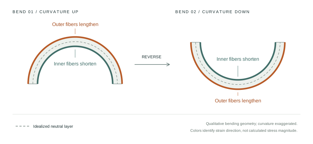
Here, t is thickness, R is the neutral-axis bend radius, σy is yield strength and E is Young’s modulus. Matching these estimates gives R ≈ Et / (2σy) at the onset of surface yielding.
Illustrative calculation: t = 2 mm, σy = 300 MPa and E = 200,000 MPa give εyield ≈ 0.0015 and R ≈ 667 mm. This estimates first yield at the surface, not a leveling setting or full-thickness yielding. A strip does not necessarily wrap to the work-roll radius. Contact geometry, tension, hardening, reverse yielding and machine stiffness matter.
Roll diameter and pitch influence achievable curvature. Backups resist work-roll deflection under load. On machines with adjustable backup flights, the operator can alter the relative path lengths across the strip to address widthwise shape. Increasing the work in the already-long, wavy region can make a shape problem worse. Bradbury explains entry plunge and backup adjustment.
A thickness rating alone is insufficient: a wider, stronger strip can demand more force than a narrower, lower-strength strip of the same thickness. Select the machine configuration and operating recipe for the actual grade, temper, yield strength, thickness and width.
Leveling describes several different routes.
| Route | Primary action | What to ask the supplier |
|---|---|---|
| Roller leveling | Alternating bending through staggered work rolls, with decreasing curvature toward the outlet. | Is the roll diameter, support and setup appropriate for this gauge and strength? |
| Tension leveling | Controlled strip tension combined with bending; often used in continuous coil processing. | What elongation, surface and shape controls apply to this grade and finish? |
| Stretcher leveling | Grips a strip segment and stretches it beyond yield across its section. | What length, grip-zone, strength and surface limitations apply? What post-cut result is agreed? |
| Temper-mill route | A controlled rolling reduction, often combined with leveling and cut-to-length processing. | How are thickness, mechanical properties, surface condition and flatness controlled? |
Some modern roller systems also control inter-roll tension. Their capability cannot be inferred from the word “roller” alone. Bradbury eDrive and Butech Bliss describe examples of drive and roll-system design choices.
Stretcher leveling is specifically intended to improve stability by plastically extending the material across its section. Red Bud describes that mechanism. Published phrases such as “memory-free” or “laser flat” should still be translated into agreed inspection criteria. No process name guarantees that every geometry will remain flat after laser heating, forming or welding.
For aluminum, stainless steel, coated products and high-strength grades, qualify the route against the actual temper and surface requirement. A process chosen for carbon plate is not automatically appropriate for thin cosmetic sheet. The supplier should explain its limits and validate the result with representative material.
Where coil leveling is documented in the United States.
Leveling capability sits inside service centers and toll processors across the country. The correct sourcing question is which facility and which process will handle your material.
This map contains 10 selected, publicly documented locations. It includes related temper-mill routes and clearly labels them. Pins represent approximate city locations, not plant entrances. The selection is not an exhaustive census, a capacity ranking, a list of Xeon suppliers, or an endorsement.
Select a numbered location
Facility details and the complete source directory appear below.
*Leveling listed: the source identifies leveling service but does not establish the exact machine configuration. All entries rely on public descriptions, not an on-site audit. Confirm current availability, material limits and the actual processing plant before ordering.
Alaska and Hawaii are shown as insets. No listed pin does not mean no local capability.
- 01 / Vancouver, WA
Bradbury eDrive roller leveling / cut-to-length
The Vancouver facility identifies cut-to-length processing for sheet and plate using a Bradbury eDrive system.
Facility source ↗ - 02 / Los Angeles, CA
Four cut-to-length leveling lines
Independent toll processor of customer-owned carbon steel coil. Its location page describes four leveling lines for different gauge and width ranges.
Facility source ↗ - 03 / Carrollton, TX
Coil leveling / cut-to-length blanking
The Dallas service center is physically in Carrollton. Its branch page lists coil leveling and precision blanking; the exact leveler configuration is not specified.
Facility source ↗ - 04 / Houston, TX
Temper-mill cut-to-length processing
Triple-S identifies the Houston operation as a temper-mill processor. This is a related flatness-control route, distinct from a standalone roller leveler.
Facility source ↗ - 05 / Minneapolis / Plymouth, MN
Stretcher leveling / cut-to-length
Olympic identifies its Minnesota coil operation separately from its plate operation and lists stretcher leveling and cut-to-length services.
Facility source ↗ - 06 / Bettendorf, IA
Temper-mill processing
The Bettendorf facility page explicitly identifies an on-site temper mill serving sheet and finished-part applications.
Facility source ↗ - 07 / Franklin, OH
Stretcher leveling + corrective multi-blanking
Greenpoint lists a Red Bud stretcher line and a separate precision multi-blanking line with corrective leveling at its Franklin service center.
Facility source ↗ · Location ↗ - 08 / Winder, GA
Stretch leveling / cut-to-length
Olympic's Southeast page lists stretch leveling under Winder's equipment. Nearby Buford is a separate operation.
Facility source ↗ - 09 / Washington, PA
Leveling / cut-to-length — stainless and aluminum
The branch is in Washington, Pennsylvania. It lists leveling for stainless and aluminum sheet and coil; confirm the processing route for the order.
Facility source ↗ - 10 / Norristown, PA
Flat-roll leveling line
The flat-roll division lists a leveling line for coils up to 60 inches wide and sheet lengths up to 12 feet.
Facility source ↗
Sources accessed September 12, 2026. Each entry links to the facility or processing page supporting it. Map boundaries: U.S. Atlas / U.S. Census Bureau cartographic boundaries; city coordinates are approximate editorial plotting locations.
A material quote is also a process decision.
A good sheet-metal vendor controls the condition of the material entering production. The benefit appears in cutting, handling, bending and assembly.
Consider a long, narrow laser-cut rail. Before the final cut, the surrounding sheet restrains it. Once separated, inherited stress and cutting heat can change its shape. Improving incoming material stability removes one source of variation; managing heat, cut sequence and part geometry remains necessary. See why laser-cut parts warp.
At the cutting table
A flatter sheet supports more consistent handling and cutting conditions. Lifted features can interfere with travel, complicate unloading and require intervention. Stable stock is especially valuable when automated handling assumes a predictable part position.
At the next operation
Unexpected bow or twist changes how a blank sits against a backgauge, fixture or mating part. Correcting it consumes labor and can introduce marks or dimensional changes. A reliable incoming condition makes downstream variation easier to diagnose.
Downstream effects are discussed by ARKU and Red Bud. The rail example is an engineering illustration, not a measured Xeon production trial.
Buy the condition of the material, the evidence behind it, and the supplier’s ability to repeat it.
A vendor may operate its own leveler or buy from a qualified processor. Either arrangement can work. What matters is traceability to the processing route, an agreed acceptance method, and a practical response when the material fails that agreement.
Compare cost per accepted part. Sheet price, yield loss, machine interruptions, secondary flattening, fixture adjustment and replacement freight all enter that cost. A small purchase-price saving has little value if it adds rework to every batch.
| Evidence to request | What it tells you |
|---|---|
| Material identity | Grade, temper, nominal and actual thickness, applicable strength range, and coil/heat traceability. |
| Processing route | The facility, machine type and material range that will actually be used. |
| Setup and maintenance | How the operator controls repeatability, supports the rolls, checks settings and protects the surface. |
| Flatness evidence | The measured condition of a free sheet using the agreed support, span and measurement method. |
| Representative cut trial | Whether application-relevant shapes remain acceptable after release from the sheet. |
| Nonconformance response | How suspect material is identified, contained, reviewed and replaced or reprocessed. |
A trial cut is application evidence. It is not a direct measurement of every residual-stress component, and it does not validate every possible nest or part geometry.
Write a result the supplier can inspect.
“Flat sheet” is incomplete as a purchase requirement. Define the inspection condition and the geometry that matters. A sheet held flat by clamps or a heavy stack does not demonstrate its free-state flatness.
- Define the material. Specify grade/alloy, temper or condition, thickness and finish. Provide required sheet dimensions and quantities.
- Define flatness. State the allowable deviation, evaluation area or span, supporting surface and whether the sheet is measured without restraint.
- Separate the tolerances. Length, width, squareness, edge camber, burr and flatness are distinct requirements. An acceptable value for one does not establish the others.
- Describe the end use. Include thin webs, long rails, open frames, cosmetic surfaces and automated loading needs.
- Agree on verification. Establish sampling, traceability and a representative cut-test acceptance method when stability after cutting matters.
A useful RFQ starting point
This is an editorial specification framework. Fill in values with the supplier for the actual application; it is not a published Xeon tolerance or a substitute for the applicable material specification.
Does leveling make the sheet thinner?
Roller leveling primarily corrects shape through bending. Stretcher leveling adds plastic elongation; a temper mill deliberately applies rolling reduction. Check thickness and mechanical-property requirements for the selected route rather than treating the processes as interchangeable.
Will properly leveled stock prevent all laser-cut warping?
No. It can improve the incoming condition, but thermal input, geometry, support and cut sequence still influence the finished part. Define a representative trial when the application is sensitive.
Does the vendor need to own a leveling line?
No. A vendor can source appropriately processed sheet through a qualified service center or toll processor. It should be able to identify that route and support its material-quality claims with agreed evidence.
Precision starts in the sheet.
The drawing defines the intended part. Material preparation determines one of the conditions under which that part will be made. A capable vendor connects those two facts through a suitable process, measured results and repeatable supply.
Discuss a material or flatness requirement with Xeon →Source notes & original CAD.
The article combines machine-builder descriptions with editorial engineering analysis. Supplier capability descriptions are self-reported and do not establish an audited quality rating. No supplier relationship or leveling capability is asserted for Xeon NC.
- ARKU — How roller leveling works: alternating bending and equipment considerations.
- Bradbury — Three-stage leveling process: entry plunge, widthwise correction and exit setup.
- Bradbury — eDrive systems: inter-roll drive and tension control.
- Butech Bliss — Roller and stretch leveling: shape defects and machine configurations.
- Red Bud — Stretcher levelers: stretching mechanism and downstream stability.
- ARKU — Leveling sheet and plate: downstream processing applications.
The illustration model
The coil, nine work rolls, strip and stacked sheets were created in Onshape for this article. The model uses a 2 mm illustrative strip, 48 mm work-roll diameter and 50 mm spacing between consecutive staggered stations. These values demonstrate geometry only. The coil is an annular envelope, not individual windings; the sheet path is prescribed, not solved from contact forces or material behavior.
Open the original Onshape model ↗ · Open the full-resolution model image ↗ · Open the Xeon NC cover drawing ↗
The mathematical example explains first yield using an idealized bending estimate. It is independent of the CAD dimensions and should not be used to set a real leveling line.