See the bend before the press brake does.
A press brake bend simulator shows how a sheet metal part forms, one stroke at a time, so you find the flange that hits the punch while it is still a sketch. The Xeon NC simulator is free, runs in the browser, and uses the same punches, dies and gauge data our shop bends with.
It works in two steps. In Build profile you draw the part's cross-section and pick a material and gauge. In Simulate the tool picks a collision-free bend order and animates each stroke in a 2D cross-section of our TRUMPF TruBend 5170S, checking the part against the punch, ram, die, lower beam and itself. When every bend is clear, export the flat pattern and quote the part.
Three ways to draw the part.
The profile is the part's cross-section, the shape you would see looking down the bend lines. Build it whichever way is fastest.
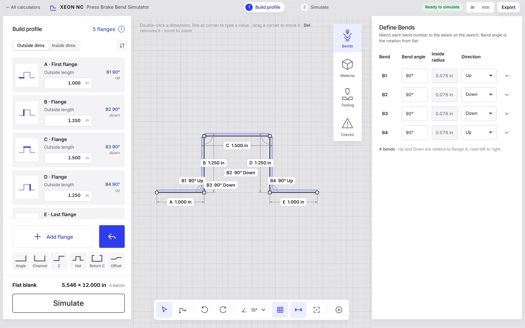
Outside or inside dimensions
Switch between Outside dims and Inside dims to match your drawing. Outside runs each flange to the outside mold line of its bends; inside runs to the inside mold line. The numbers stay the same when you switch and the part redraws, so pick the convention your print uses before you type lengths.
Bend angle and direction
In Define Bends, the bend angle is the rotation from flat, so a 90° bend makes a square corner. Up and Down are relative to flange A, read left to right. Each bend is labeled B1, B2 and so on, on the sketch and in the table.
The gauge loads the shop's tooling.
Open Material, choose a material and thickness, and set the bend length (the part's width along the bend). Each stocked gauge pins the die, punch, inside radius and K-factor the shop runs.
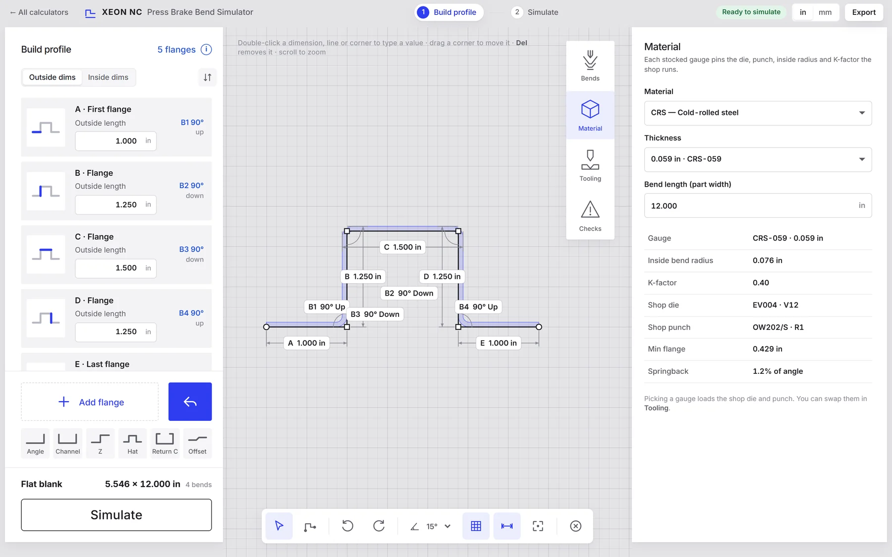
The panel lists cold-rolled, 4130 chromoly, galvanized, hot-rolled pickled and oiled, 304 and 316 stainless, and 2024 and 5052 aluminum. The inside radius and K-factor it shows are what the flat pattern is developed with; the K-factor guide explains how they set the blank size, and the tooling library shows each die and punch.
Watch every stroke, in order.
Press Simulate. The bends are auto-sequenced into a collision-free order, then each one plays out on the press: the approach, the bend with overbend, springback, and the return.
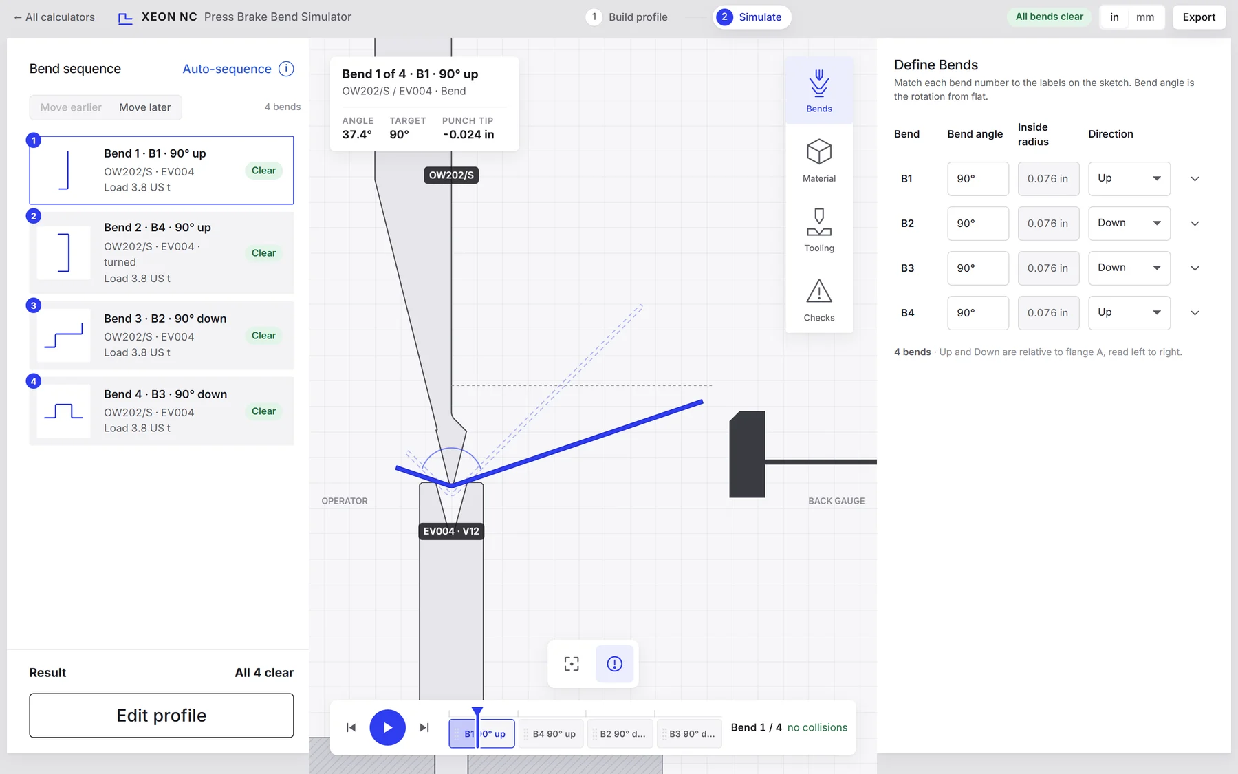
To try a different order, select a bend and use Move earlier or Move later. Every bend is re-checked. Auto-sequence puts the planner's order back.
When a flange hits the punch.
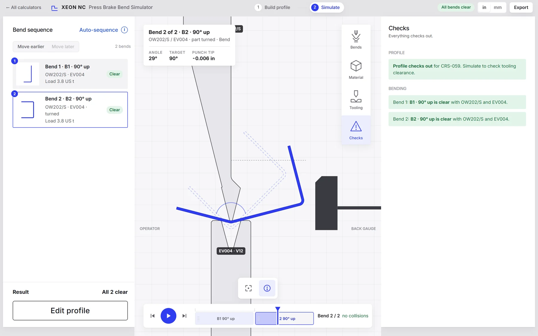
A collision turns the bend red in the sequence and on the timeline, and the status at the top reads how many bends have problems. Open Checks to see what hit what, at what angle, and what to try next.
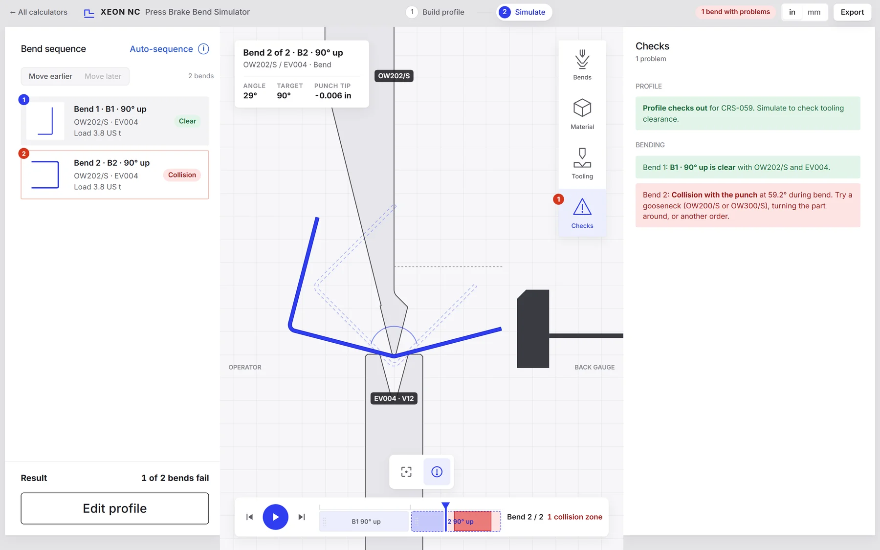
Here, the first flange swings up into the punch on the second bend. We tried what Checks suggested: the OW200/S and OW300/S gooseneck punches did not clear this channel in the simulator. The fix was the part. With the flanges shortened to 1.5 in, both bends clear on the standard punch.
Try another punch or die.
Open Tooling to change the punch or die for the selected bend. Each tool is marked Clear or not for that bend, and the shop's pick is labeled.
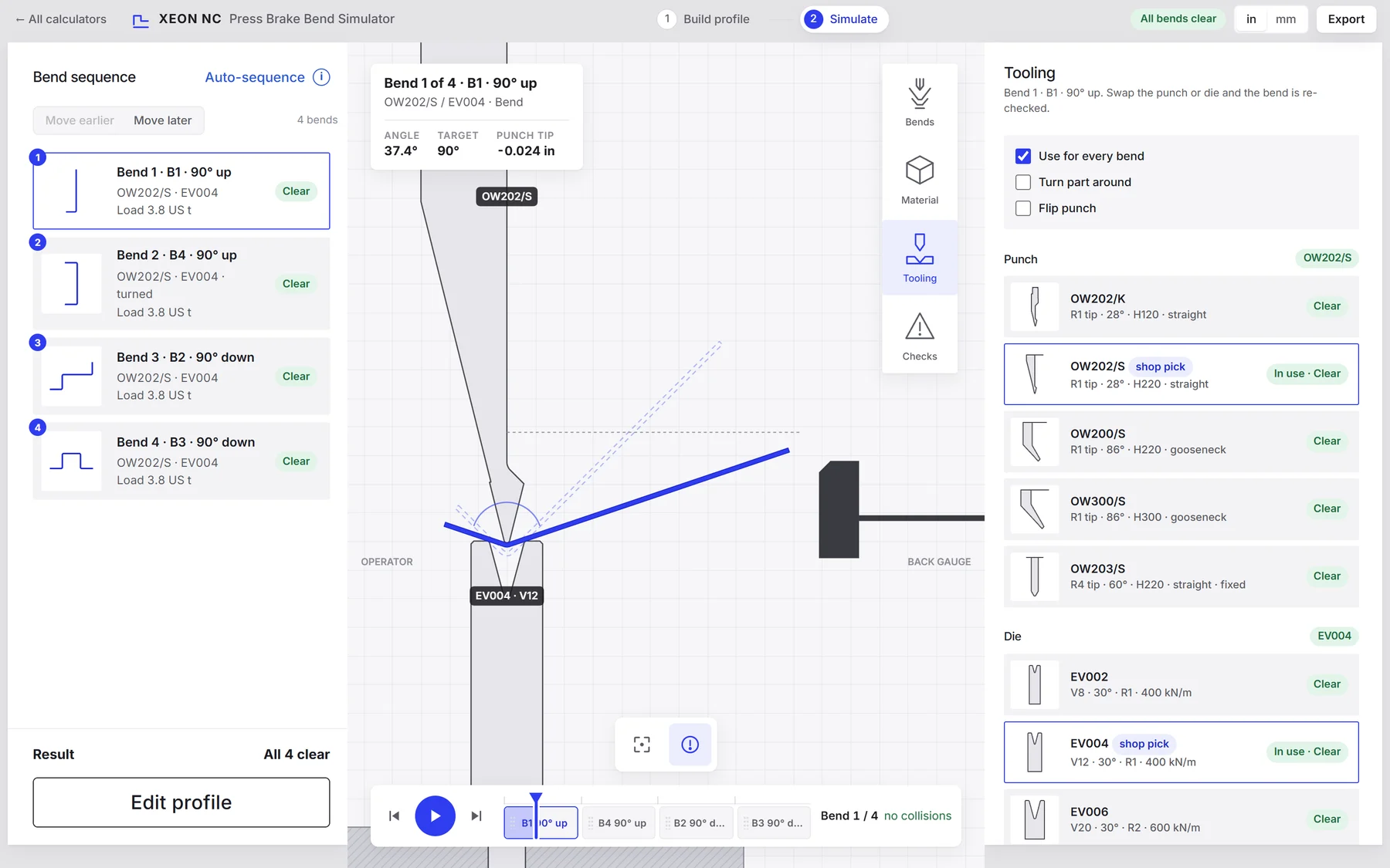
The punches include the straight OW202/S and OW202/K, the OW200/S and OW300/S goosenecks, and the OW203/S with an R4 tip. The dies run from the EV002 V8 to the W50/80 V50. Three options at the top change how every bend is set up: Use for every bend, Turn part around and Flip punch.
Take the flat pattern with you.
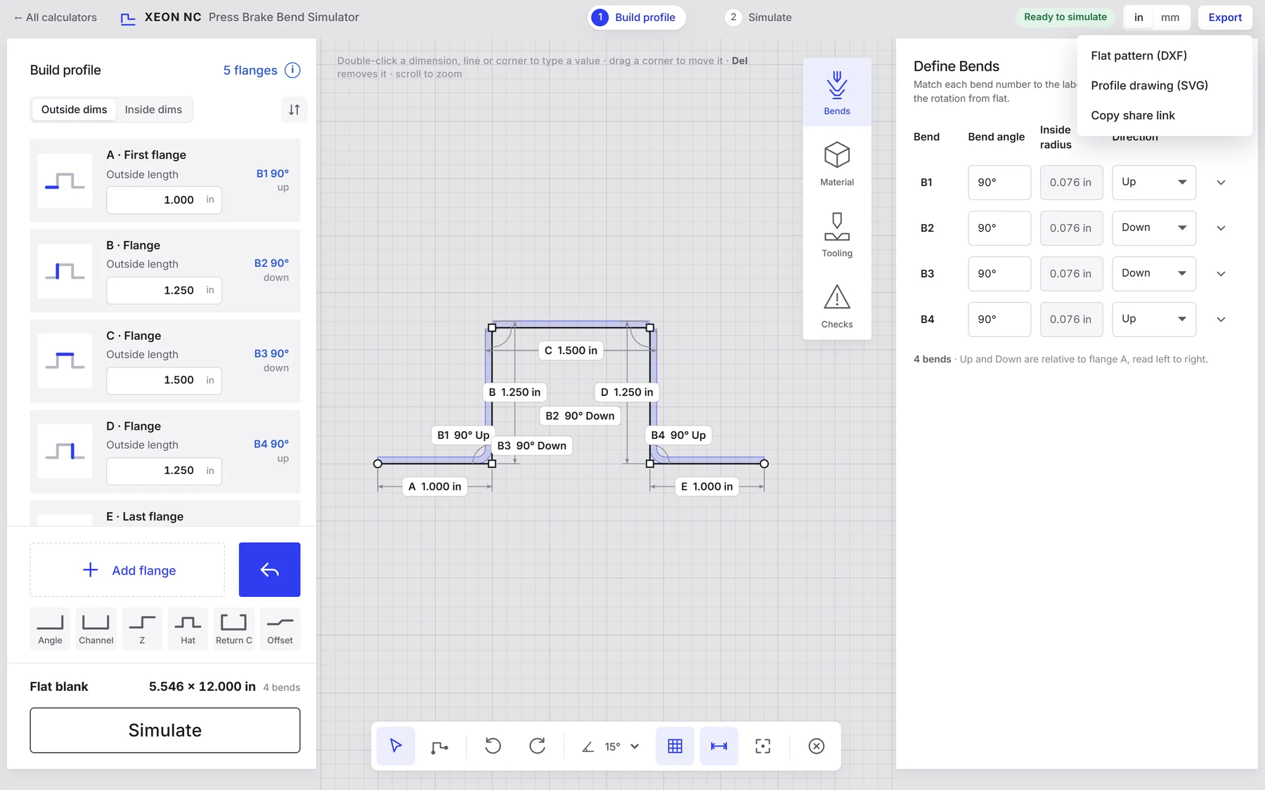
Flat pattern (DXF) downloads the developed blank, sized with the gauge's inside radius and K-factor. Profile drawing (SVG) saves the dimensioned cross-section. Copy share link copies a link that reopens the exact design, material and tooling, which is handy for sending to a colleague or to us.
To order, upload the part to the instant quote. A formed STEP is the safest file, because we develop the flat pattern from the bend data for the die that runs your job; see STEP vs. DXF.
A 2D check, not a sign-off.
The simulator answers one question well: will this cross-section form on these tools in this order? It is not a full manufacturability review.
- 2D only. Holes near bends, box corners, tabs and anything that varies along the bend line are not simulated. See the hole-to-bend distance guide and the corner relief guide.
- Some values are estimated. Springback for 4130, hot-rolled, 316 and 2024 is estimated. Tensile strength is approximated from the gauge table's force factor. Off the gauge's own die, the inside radius is taken as 0.16 × the V-opening.
- Minimum flange is a rule. It uses 0.7 × V + punch tip + thickness, a screening value, not a measured limit.
- Every order is still reviewed. Passing in the simulator does not replace the manufacturability review each job gets before production.
Bend simulator, answered.
Is the Xeon NC bend simulator free?
Yes. It runs in your browser with no account and no download. Open bend-simulator.html, sketch a profile and simulate it.
What does a press brake bend simulator do?
It shows how a sheet metal part will form on the press brake before anyone cuts metal. The Xeon NC simulator unfolds your profile, picks a bend order, and animates every bend in a 2D cross-section of the TruBend 5170S, checking the part against the punch, ram, die, lower beam and itself.
Which tools and materials does it use?
The punches and dies are the TRUMPF tools in the Xeon NC tooling library, such as the OW202/S punch and EV004 die. Picking a material and gauge loads the die, punch, inside radius and K-factor the shop runs for that gauge. Swap tools in the Tooling panel and every bend is re-checked.
Can I export a flat pattern?
Yes. The Export menu downloads the flat pattern as a DXF and the profile drawing as an SVG, and copies a share link that reopens the same design.
What should I do when a bend collides?
Open Checks to see which bend collides, with what, and at what angle, plus what to try: a gooseneck punch, turning the part around, flipping the punch or another bend order. If nothing clears, change the part. In our example, a 2 in by 2 in channel collides, and shortening the flanges to 1.5 in clears it.
Does a clear simulation guarantee my part can be made?
No. It is a 2D check of the profile and tooling, not a full 3D review. Holes near bends, box corners and features along the bend line are not simulated, and some springback values are estimates. Every order still gets a manufacturability review before production.
How is this different from a 3D bend preview?
A 3D preview shows the finished shape. The simulator shows the forming: the punch coming down, the flanges swinging up, and where they hit the tooling, bend by bend, in the order the press brake would run them.
Bends clear? Upload the part.
Pick the material and thickness when you upload. The flat pattern is developed against the die that runs the job.
Get an instant quote →