← Back to Manufacturing Insights
01 / The Short Answer
K is where the sheet neither stretches nor squeezes.
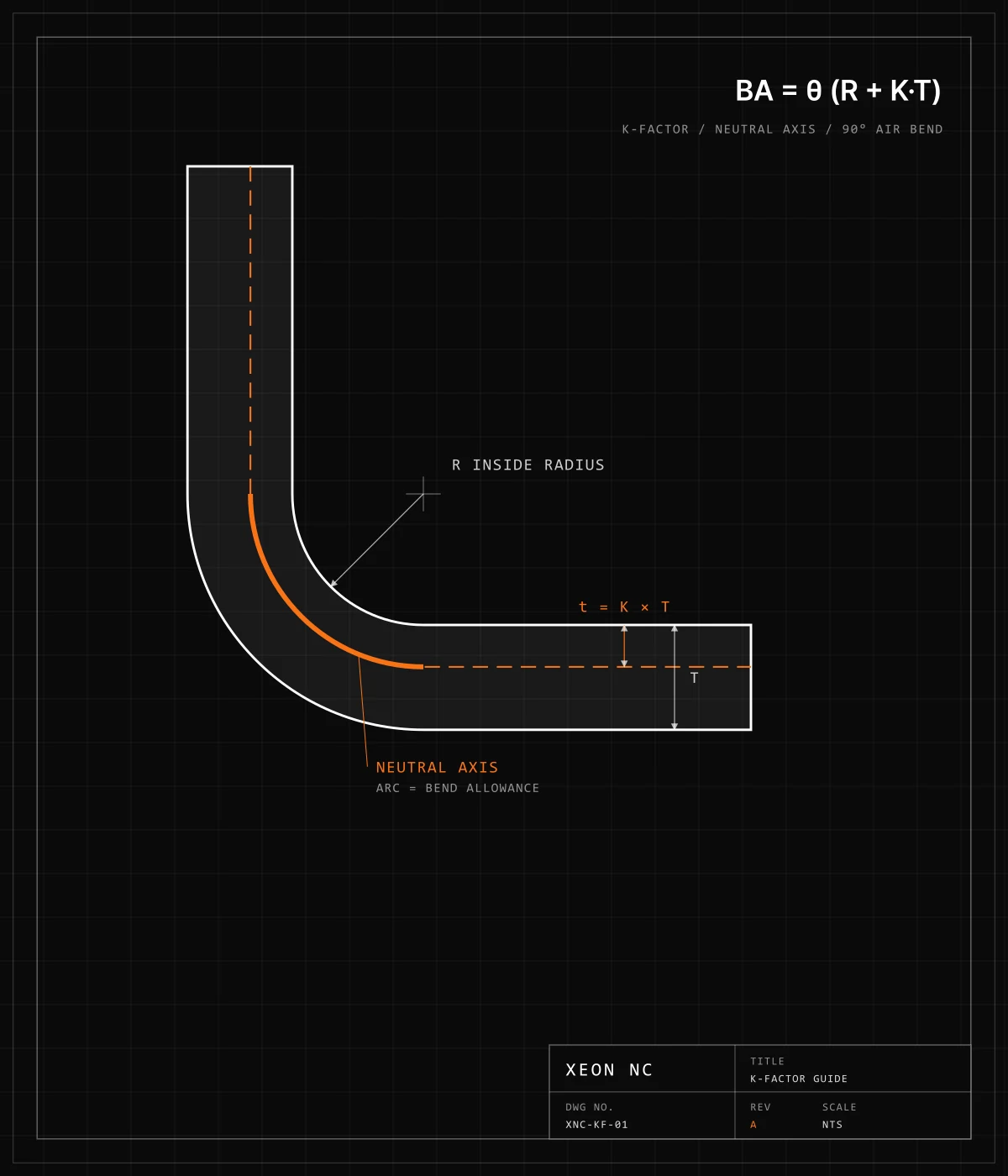
The K-factor is the position of the neutral axis inside a bend, written as a fraction of the sheet thickness. When sheet bends, the inside compresses and the outside stretches. Between them is a layer that does neither, and its distance from the inside surface, t, divided by the thickness, T, is the K-factor.
CAD uses that number to work out how much flat material each bend consumes, the bend allowance, and therefore how big to cut the blank. A K of 0.5 would put the neutral axis at mid-thickness. In real air bends it sits closer to the inside, so practical values are lower: every value in our production bend table falls between 0.32 and 0.48.
The K-factor is not a material property. It belongs to a material, a thickness, a radius and a die.
Use the shop's number.A CAD default or a generic chart gives a plausible flat pattern that can still be the wrong size. The
chart below lists the values we bend with, next to the radius and die each one belongs to.
02 / The Neutral Axis
The one length that survives the bend.
Every fiber inside the bend changes length except one. The neutral axis keeps its flat length, so the flat blank equals the straight segments plus the neutral-axis arc through each bend.
01 / Cross-section / 90° air bend
Neutral axis at K × T
K = 0.40 shown
The dashed orange line is the neutral axis. Its radius is the inside radius plus K × T. The solid orange arc is the bend allowance.
What it controls
The flat length of every bent part. Neutral radius = R + K × T, and the arc at that radius is what the bend adds to the blank.
What it is not
Not a fixed property of aluminum or steel. The same alloy gets a different K at a different thickness, radius or die.
04 / Worked Example
0.100″ 5052-H32, bent to 90°.
The same row the technical drawing guide develops its bracket from. Our table sets the inside radius at 0.126″ and K at 0.40, on a 20 mm die.
Thickness T0.100 in
Inside radius R0.126 in
K-factor0.40
Bend angle θ90° = π/2
Bend allowance0.2608 in
Outside setback0.2260 in
Bend deduction0.1912 in
Table BD 90°0.1912 in
01
Bend allowance
BA = π/2 × (0.126 + 0.40 × 0.100) = π/2 × 0.166 = 0.2608″
02
Outside setback
OSSB = (0.126 + 0.100) × tan 45° = 0.2260″
03
Bend deduction
BD = 2 × 0.2260 − 0.2608 = 0.1912″, which matches the 0.1912″ in our bend table.
04
Flat length
Two hypothetical 2.000″ outside legs develop to 2.000 + 2.000 − 0.1912 = 3.8088″.
What a wrong K costs.Model the same bend with a 0.45 default and the bend allowance grows to 0.2686″, about 0.008″ more per 90° bend. A four-bend tray picks up roughly 0.031″ across its blank, enough to push a tight fit out of tolerance.
05 / K-Factor Chart
The K-factors we bend with.
59 production values from our bend table, grouped by the material family each one was calibrated for. Every row assumes a 90° air bend with the V-die shown; BA is calculated from the row, BD is the table value.
Aluminum
K 0.37–0.48 · 15 thicknesses
Applies to: 5052-H32, 6061-T6, 1100-H14, 7075-T6 · Material pages: 5052-H32 Aluminum, 6061-T6 Aluminum, 7075-T6 Aluminum, 1100-H14 Aluminum
Aluminum K-factors by thickness, with inside radius, V-die, bend allowance and bend deduction for a 90 degree air bend
| Thickness | Inside radius | V-die | K-factor | BA 90° | BD 90° | Min. flange |
|---|
| 0.020″ 0.51 mm | 0.050″ | 8 mm | 0.45 | 0.0927″ | 0.0475″ | 0.198″ |
| 0.032″ 0.81 mm | 0.050″ | 8 mm | 0.45 | 0.1012″ | 0.0630″ | 0.198″ |
| 0.040″ 1.02 mm | 0.050″ | 8 mm | 0.45 | 0.1068″ | 0.0734″ | 0.198″ |
| 0.050″ 1.27 mm | 0.076″ | 12 mm | 0.45 | 0.1547″ | 0.0971″ | 0.298″ |
| 0.063″ 1.60 mm | 0.076″ | 12 mm | 0.42 | 0.1609″ | 0.1169″ | 0.298″ |
| 0.080″ 2.03 mm | 0.126″ | 20 mm | 0.48 | 0.2582″ | 0.1538″ | 0.496″ |
| 0.090″ 2.29 mm | 0.126″ | 20 mm | 0.37 | 0.2502″ | 0.1818″ | 0.496″ |
| 0.100″ 2.54 mm | 0.126″ | 20 mm | 0.40 | 0.2608″ | 0.1912″ | 0.496″ |
| 0.125″ 3.17 mm | 0.189″ | 30 mm | 0.44 | 0.3833″ | 0.2447″ | 0.744″ |
| 0.160″ 4.06 mm | 0.189″ | 30 mm | 0.43 | 0.4050″ | 0.2930″ | 0.744″ |
| 0.188″ 4.78 mm | 0.189″ | 30 mm | 0.43 | 0.4239″ | 0.3301″ | 0.744″ |
| 0.250″ 6.35 mm | 0.315″ | 50 mm | 0.42 | 0.6597″ | 0.4702″ | 1.240″ |
| 0.375″ 9.52 mm | 0.315″ | 50 mm | 0.42 | 0.7422″ | 0.6378″ | 1.240″ |
| 0.500″ 12.70 mm | 0.315″ | 50 mm | 0.42 | 0.8247″ | 0.8053″ | 1.240″ |
| 0.750″ 19.05 mm | 0.315″ | 50 mm | 0.42 | 0.9896″ | 1.1404″ | 1.240″ |
Cold-rolled steel
K 0.32–0.40 · 10 thicknesses
Applies to: A1008 CR · Material pages: A1008 Cold-Rolled Steel
Cold-rolled steel K-factors by thickness, with inside radius, V-die, bend allowance and bend deduction for a 90 degree air bend
| Thickness | Inside radius | V-die | K-factor | BA 90° | BD 90° | Min. flange |
|---|
| 0.024″ 0.61 mm | 0.050″ | 8 mm | 0.38 | 0.0929″ | 0.0552″ | 0.198″ |
| 0.030″ 0.76 mm | 0.050″ | 8 mm | 0.38 | 0.0964″ | 0.0637″ | 0.198″ |
| 0.036″ 0.91 mm | 0.050″ | 8 mm | 0.38 | 0.1000″ | 0.0721″ | 0.198″ |
| 0.048″ 1.22 mm | 0.050″ | 8 mm | 0.38 | 0.1072″ | 0.0887″ | 0.198″ |
| 0.060″ 1.52 mm | 0.076″ | 12 mm | 0.40 | 0.1571″ | 0.1147″ | 0.298″ |
| 0.075″ 1.90 mm | 0.076″ | 12 mm | 0.40 | 0.1665″ | 0.1353″ | 0.298″ |
| 0.090″ 2.29 mm | 0.126″ | 20 mm | 0.34 | 0.2460″ | 0.1860″ | 0.496″ |
| 0.100″ 2.54 mm | 0.126″ | 20 mm | 0.34 | 0.2513″ | 0.2007″ | 0.496″ |
| 0.120″ 3.05 mm | 0.126″ | 20 mm | 0.38 | 0.2695″ | 0.2224″ | 0.496″ |
| 0.135″ 3.43 mm | 0.189″ | 30 mm | 0.32 | 0.3647″ | 0.2833″ | 0.744″ |
Hot-rolled steel
K 0.36 · 9 thicknesses
Applies to: A36 / A1011 HR, Corten (A588 / A606), AR500 · Material pages: A36 / A1011 Hot-Rolled, P&O, A36 / A1011 Hot-Rolled, Mill Finish, Corten Weathering Steel, AR500 Abrasion-Resistant Steel
Hot-rolled steel K-factors by thickness, with inside radius, V-die, bend allowance and bend deduction for a 90 degree air bend
| Thickness | Inside radius | V-die | K-factor | BA 90° | BD 90° | Min. flange |
|---|
| 0.060″ 1.52 mm | 0.076″ | 12 mm | 0.36 | 0.1533″ | 0.1185″ | 0.298″ |
| 0.075″ 1.90 mm | 0.076″ | 12 mm | 0.36 | 0.1618″ | 0.1400″ | 0.298″ |
| 0.100″ 2.54 mm | 0.126″ | 20 mm | 0.36 | 0.2545″ | 0.1975″ | 0.496″ |
| 0.120″ 3.05 mm | 0.126″ | 20 mm | 0.36 | 0.2658″ | 0.2262″ | 0.496″ |
| 0.135″ 3.43 mm | 0.189″ | 30 mm | 0.36 | 0.3732″ | 0.2748″ | 0.744″ |
| 0.188″ 4.78 mm | 0.189″ | 30 mm | 0.36 | 0.4032″ | 0.3508″ | 0.744″ |
| 0.250″ 6.35 mm | 0.315″ | 50 mm | 0.36 | 0.6362″ | 0.4938″ | 1.240″ |
| 0.313″ 7.95 mm | 0.315″ | 50 mm | 0.36 | 0.6718″ | 0.5842″ | 1.240″ |
| 0.375″ 9.52 mm | 0.315″ | 50 mm | 0.36 | 0.7069″ | 0.6731″ | 1.240″ |
Galvanized steel
K 0.36–0.40 · 6 thicknesses
Applies to: G90 galvanized, A1008 electro-galvanized · Material pages: A1008 Electro-Galvanized Steel, G90 Galvanized Steel
Galvanized steel K-factors by thickness, with inside radius, V-die, bend allowance and bend deduction for a 90 degree air bend
| Thickness | Inside radius | V-die | K-factor | BA 90° | BD 90° | Min. flange |
|---|
| 0.024″ 0.61 mm | 0.050″ | 8 mm | 0.38 | 0.0929″ | 0.0552″ | 0.198″ |
| 0.036″ 0.91 mm | 0.050″ | 8 mm | 0.38 | 0.1000″ | 0.0721″ | 0.198″ |
| 0.048″ 1.22 mm | 0.050″ | 8 mm | 0.38 | 0.1072″ | 0.0887″ | 0.198″ |
| 0.060″ 1.52 mm | 0.076″ | 12 mm | 0.36 | 0.1533″ | 0.1185″ | 0.298″ |
| 0.075″ 1.90 mm | 0.076″ | 12 mm | 0.40 | 0.1665″ | 0.1353″ | 0.298″ |
| 0.135″ 3.43 mm | 0.189″ | 30 mm | 0.40 | 0.3817″ | 0.2663″ | 0.744″ |
304 stainless
K 0.34–0.38 · 10 thicknesses
Applies to: 304 · Material pages: 304 Stainless Steel
304 stainless K-factors by thickness, with inside radius, V-die, bend allowance and bend deduction for a 90 degree air bend
| Thickness | Inside radius | V-die | K-factor | BA 90° | BD 90° | Min. flange |
|---|
| 0.024″ 0.61 mm | 0.050″ | 8 mm | 0.36 | 0.0921″ | 0.0561″ | 0.198″ |
| 0.036″ 0.91 mm | 0.050″ | 8 mm | 0.36 | 0.0989″ | 0.0733″ | 0.198″ |
| 0.048″ 1.22 mm | 0.050″ | 8 mm | 0.36 | 0.1057″ | 0.0905″ | 0.198″ |
| 0.060″ 1.52 mm | 0.076″ | 12 mm | 0.34 | 0.1514″ | 0.1204″ | 0.298″ |
| 0.075″ 1.90 mm | 0.076″ | 12 mm | 0.36 | 0.1618″ | 0.1400″ | 0.298″ |
| 0.100″ 2.54 mm | 0.126″ | 20 mm | 0.36 | 0.2545″ | 0.1975″ | 0.496″ |
| 0.120″ 3.05 mm | 0.126″ | 20 mm | 0.38 | 0.2695″ | 0.2224″ | 0.496″ |
| 0.135″ 3.43 mm | 0.189″ | 30 mm | 0.38 | 0.3775″ | 0.2705″ | 0.744″ |
| 0.188″ 4.78 mm | 0.189″ | 30 mm | 0.35 | 0.4002″ | 0.3538″ | 0.744″ |
| 0.250″ 6.35 mm | 0.315″ | 50 mm | 0.34 | 0.6283″ | 0.5017″ | 1.240″ |
316 stainless
K 0.34–0.38 · 9 thicknesses
Applies to: 316 · Material pages: 316 Stainless Steel
316 stainless K-factors by thickness, with inside radius, V-die, bend allowance and bend deduction for a 90 degree air bend
| Thickness | Inside radius | V-die | K-factor | BA 90° | BD 90° | Min. flange |
|---|
| 0.036″ 0.91 mm | 0.050″ | 8 mm | 0.34 | 0.0978″ | 0.0744″ | 0.198″ |
| 0.048″ 1.22 mm | 0.050″ | 8 mm | 0.34 | 0.1042″ | 0.0920″ | 0.198″ |
| 0.060″ 1.52 mm | 0.076″ | 12 mm | 0.34 | 0.1514″ | 0.1204″ | 0.298″ |
| 0.075″ 1.90 mm | 0.076″ | 12 mm | 0.34 | 0.1594″ | 0.1424″ | 0.298″ |
| 0.100″ 2.54 mm | 0.126″ | 20 mm | 0.38 | 0.2576″ | 0.1944″ | 0.496″ |
| 0.120″ 3.05 mm | 0.126″ | 20 mm | 0.38 | 0.2695″ | 0.2224″ | 0.496″ |
| 0.135″ 3.43 mm | 0.189″ | 30 mm | 0.38 | 0.3775″ | 0.2705″ | 0.744″ |
| 0.188″ 4.78 mm | 0.189″ | 30 mm | 0.35 | 0.4002″ | 0.3538″ | 0.744″ |
| 0.250″ 6.35 mm | 0.315″ | 50 mm | 0.34 | 0.6283″ | 0.5017″ | 1.240″ |
Source: Xeon NC production bend table (TRUMPF press brake tooling), the same data behind the bend allowance calculator and the bending ontology guide. Values are for the listed thickness and die. A different die changes the radius, and with it the K-factor and bend deduction. Find each die in the press brake tooling library.
06 / Why K Changes
Four things move the neutral axis.
A K-factor is only good for the conditions it was calibrated under. Change one of these and the flat pattern moves with it.
K-FACTOR / WHAT MOVES ITAIR BENDING
01 R/T
Radius versus thickness. Tight bends compress the inside harder and pull the neutral axis toward it, lowering K. As the inside radius grows relative to the thickness, K approaches 0.5.
Geometry
02 DIE
The die opening. In air bending the radius forms from the V-opening, about 0.16 × V in our table. A different die is a different radius, so the K and the deduction change too.
Tooling
03 ALLOY
Material and temper. Each family yields differently, which is why aluminum, cold-rolled, hot-rolled, galvanized and both stainless grades are calibrated separately.
Material
04 PROCESS
How the bend is made. Air bending, bottoming and coining leave different radii. Our values are for air bending on the listed die.
Method
The calibrated values also do not follow a smooth curve. On the same 20 mm die, 0.080″ 5052 bends at K = 0.48 and 0.090″ at 0.37. Look up the row for your thickness instead of interpolating between neighbors.
07 / Measure Your Own
Back out K from a test bend.
When you need a value our table does not cover, measure it. One bent coupon of known flat length gives you the bend deduction, and the formulas give you K.
01
Cut a coupon of known length
Same material lot, temper and thickness as the part. Measure the actual thickness and the blank length L.
02
Bend it with production tooling
Use the die and punch that will run the job. Measure the final angle and both outside legs, A and B, to the virtual sharp.
03
Calculate the deduction and allowance
BD = A + B − L. Then BA = 2 × (R + T) × tan(θ/2) − BD.
04
Solve for K
K = (BA / θ − R) / T. For our worked example, a 3.809″ blank bent into two 2.000″ legs gives BD = 0.191″, BA = 0.261″ and K ≈ 0.40. Bend at least three coupons and average them.
R and K travel together.The K you calculate depends on the radius you assume. On 0.100″ sheet, assuming a radius 0.005″ larger lowers the calculated K by 0.05. Record the radius with the K-factor, and enter both in CAD.
08 / Set It in CAD
Replace the default before you export.
Every sheet metal CAD system ships with a default K-factor. Set it, and the inside radius, from the row for your material and thickness before you make a flat pattern.
| CAD system | Where the K-factor lives |
|---|
| Onshape | The Sheet Metal Model feature sets thickness, bend radius and K Factor. The default is 0.45. Check Modify joint features too: they can override the model value on a single bend. |
| SolidWorks | In the Sheet-Metal feature, set Bend Allowance to K-Factor and enter the value, or point it at a gauge or bend table that carries it. |
| Fusion | Sheet Metal Rules hold the thickness, bend radius and K factor. Edit the rule assigned to the body, not just the active default. |
Then decide what you send. Upload the formed STEP when you can: we develop the flat pattern from the bend data for the die that runs your job. If you upload a flat DXF, the blank is cut as drawn, so the K-factor you used sets the finished flange lengths. See STEP vs. DXF and the Onshape STEP export guide.
09 / Questions
K-factor, answered.
What is the K-factor in sheet metal?
The K-factor is the position of the neutral axis inside a bend, written as a fraction of the sheet thickness: K = t / T, where t is the distance from the inside surface to the neutral axis and T is the thickness. CAD uses it to calculate how much flat material each bend consumes, which sets the size of the flat blank.
What is a typical K-factor?
For air bending, most values fall roughly between 0.3 and 0.5. Every value in the Xeon NC production bend table is between 0.32 and 0.48: aluminum 0.37–0.48, cold-rolled steel 0.32–0.40, hot-rolled steel 0.36, galvanized 0.36–0.40, 304 stainless 0.34–0.38 and 316 stainless 0.34–0.38.
What K-factor should I use for aluminum?
Use the value for your exact thickness. In our table the 5052-H32 family runs from 0.37–0.48; for example, 0.100 in 5052-H32 bends with a 0.126 in inside radius and K = 0.40. 6061-T6, 1100-H14, 7075-T6 use the same family table.
What K-factor should I use for steel and stainless steel?
In our table, cold-rolled A1008 runs 0.32–0.40, hot-rolled A36 / A1011 is 0.36 at every thickness, 304 stainless runs 0.34–0.38 and 316 stainless 0.34–0.38. Each value goes with the inside radius and V-die listed beside it.
Can the K-factor be greater than 0.5?
Not in ordinary bending. The inside of the bend compresses and the outside stretches, and the neutral axis moves toward the inside, so K stays at or below 0.5. Values get closer to 0.5 as the inside radius becomes large compared with the thickness.
What is the difference between the K-factor, bend allowance and bend deduction?
The K-factor locates the neutral axis. Bend allowance is the length of the neutral axis through the bend: BA = θ × (R + K × T), with θ in radians. Bend deduction is what you subtract from the two outside leg lengths to get the flat length: BD = 2 × (R + T) × tan(θ/2) − BA. One K-factor and radius define both.
What is the Y-factor?
The Y-factor is an alternative way some CAD systems express the same neutral-axis position: Y = K × π / 2. A K-factor of 0.40 is a Y-factor of about 0.628.
Do I need to match the Xeon NC K-factor in my CAD model?
If you upload a formed STEP file, we develop the flat pattern from the bend data for the die that will run your job. If you upload a flat DXF, the blank is cut as drawn, so the K-factor and radius you used set the finished flange lengths. Matching the row in our chart keeps your CAD flat pattern and ours the same.
K-factor set / quote next
Upload the formed STEP. We unfold it with these numbers.
Pick the material and thickness when you upload. The flat pattern is developed against the die that will run the job, so the flanges come out the length you modeled.
Upload your STEP →