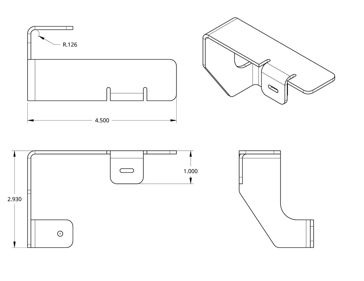
A prototype should answer a specific question
Sheet metal prototyping means making an initial part or small set of parts to evaluate a design before a larger commitment. The useful result is not just a physical object. It is evidence about fit, assembly, material behavior or the manufacturing route, tied to a known revision.
For a laser-cut and bent bracket, the question might be whether a cable clears a flange or whether a tool can reach a fastener. For an enclosure, it might be whether the cover seats correctly after finishing. Write down what must be learned before choosing the prototype's material, finish and inspection effort.
A geometry mock-up can answer a clearance question without proving strength or corrosion resistance. A functional prototype needs material and process choices appropriate to the function being tested. A single successful sample also does not establish repeatability across a production run.
Define, make, verify, then control the revision
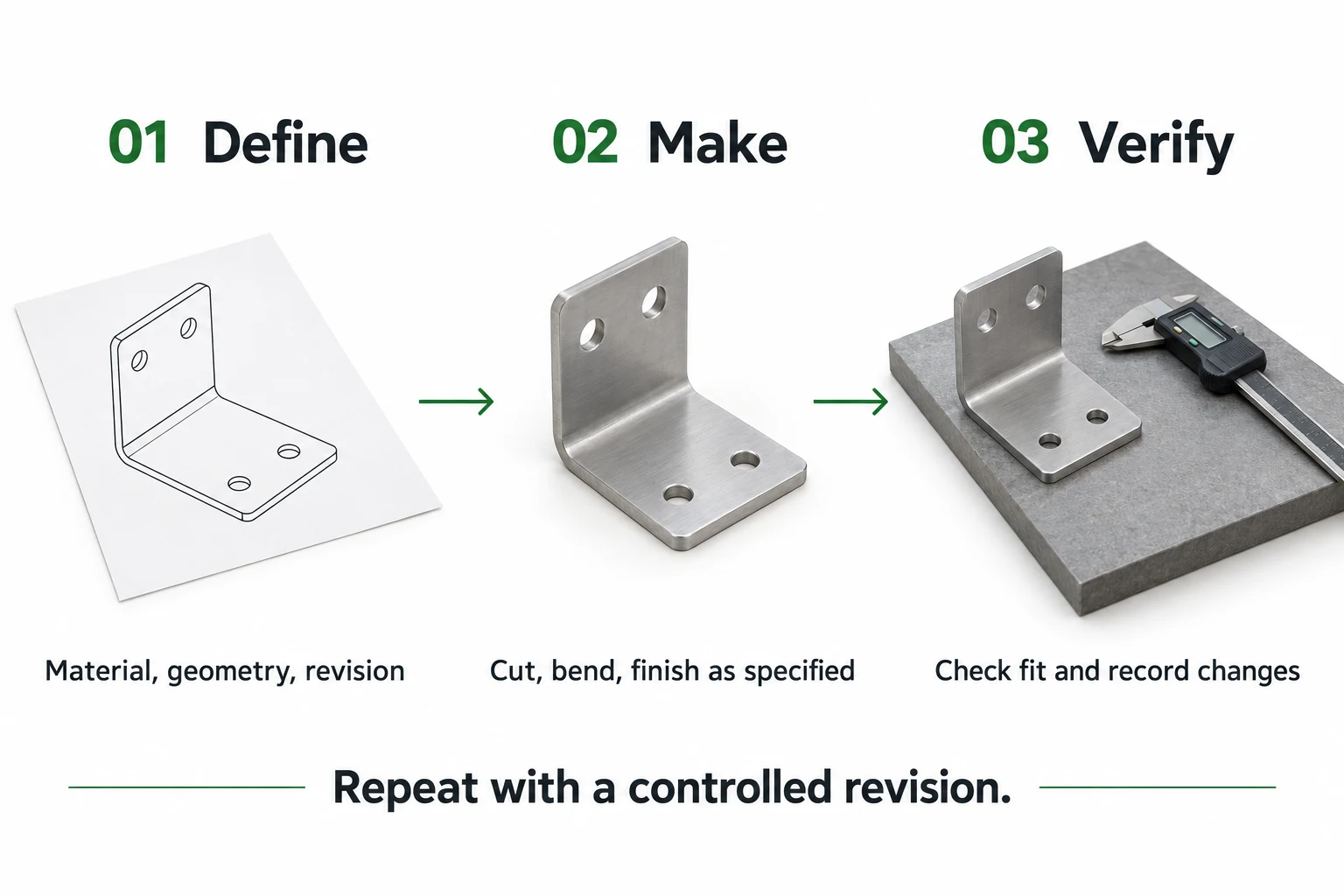
- Define: choose the test, material condition, geometry, quantity and revision. Identify the interfaces that matter.
- Make: agree on the cutting, forming and finishing route. Record any departure from the intended production process.
- Verify: compare the part with the drawing and the assembly. Record results, update the design and issue a new revision for the next iteration.
Keep the scope narrow enough that a result is interpretable. If you change material, thickness, bend geometry and finish at the same time, a better-fitting second sample will not tell you which change mattered.
Review the material and bends before cutting
Specify the alloy or grade, temper where applicable, and decimal thickness. The same gauge number can mean different thicknesses in different metals; use our sheet metal gauge chart to check the conversion. Confirm the actual stock for the quote.
For aluminum, the 5052 vs 6061 comparison explains why a formed sheet part and a machined part can lead to different material choices. A plastic print or a softer-metal mock-up may help with fit, but its behavior does not validate the final metal condition.
- Bends: review inside radii, flange length, bend sequence and tool access with the fabricator.
- Nearby features: flag holes, slots, notches and cosmetic edges near bends for review rather than assuming the flat geometry will remain unchanged.
- Interfaces: identify mounting faces, mating hole patterns and clearance for installation tools.
- Finish: include the intended finish when it matters to fit, appearance or the test.
The bend allowance calculator can support an initial layout. Its result depends on the inputs. Agree on the production bend data before treating an exported flat pattern as ready to cut.
Send a quote package that describes the finished part
A clean profile file describes the cut outline. It does not by itself communicate every requirement of a bent, threaded or finished part. Follow our CAD file preparation guide and include the information needed for each operation.
| Item | What to specify |
|---|---|
| Part file | Supported CAD format, correct units and scale, clean geometry, matching part number and revision. |
| Finished-part drawing | Bend directions, inside radii, finished dimensions, critical tolerances and secondary operations. |
| Material and finish | Grade or alloy, temper if relevant, thickness, finish and cosmetic requirements. |
| Quantity and schedule | Prototype quantity, requested delivery date and any separate future production quantity. |
| Acceptance checks | Critical interfaces, required documentation and any agreed inspection or testing requirements. |
For a flat profile, start with sheet metal laser cutting. For a formed part, include the bending requirements. Use a custom quote request when a drawing review or an operation not listed online is needed.
Inspect the first part against the test you defined
Check the received part number and revision first. Then evaluate the specified dimensions and assembly interfaces with suitable measurement methods. Record observations separately from conclusions: a cover that does not seat could involve the cover, the tray, the fasteners or the coating, not just one bend.
Example: an enclosure cover that will not seat
In this hypothetical test, the bare cover seats on the tray, but the finished assembly binds. Preserve both revisions and compare the coating requirements, measured mating features and assembly sequence before enlarging every hole. Update the affected requirement in the model and drawing together, then test the revised interface. Do not quietly alter the manufacturing file while leaving the drawing unchanged.
Keep the quote, CAD, drawing, inspection notes and photographs associated with the same revision. A controlled release helps prevent an old file from being reused; Onshape's release-management documentation describes approval and revision tracking for CAD data.
Once the design works, use our prototype-to-production release guide for the next decision: whether the definition and process are ready to repeat. That is a separate step from making the first useful prototype.
What affects prototype cost and timing?
Compare the full manufacturing route, not only the sheet area. Material availability, cut geometry, setup, bend complexity, secondary operations, finish, inspection and shipping all belong in the quote. A small quantity can still require careful programming and setup.
Ask for a prototype quote and, when useful, a separate quote at the expected production quantity. Keep the specification consistent so the comparison is meaningful. Do not assume the prototype's unit cost will apply unchanged to a larger run.
Timing must be confirmed for the actual material and operations. Resolve missing information early, and distinguish manufacturing time from finishing and delivery. Our commercial prototyping service connects the initial part to later production planning.
Common questions
Should a prototype use the final material?
Use it when the test depends on that material's behavior. A substitute may be reasonable for an early geometry check, provided the limitation is recorded and the final material is validated separately.
Is a flat DXF enough for a bent part?
It is not a complete finished-part definition by itself. Supply the required bend information and drawing, and confirm who is responsible for developing the flat pattern.
How many prototypes do I need?
Base the quantity on the questions, assembly trials and any agreed testing requirements. A fit check and a destructive test may require different samples. There is no single count that validates every design.
Further reading
- Xeon NC CAD file preparation guide: preparing the manufacturing file.
- Onshape release management: approved changes, revision status and traceability.
- Real Xeon NC metal part examples: completed brackets, plates and profiles, with quoting notes.
Bring your part to the next step.
Send your material, thickness, quantity and current design. Include a drawing for bends, secondary operations or critical dimensions.