Xeon NC / SheetForm preview / Direct application test
Make forming access part of the design conversation.
Every bend changes the geometry available for the next operation.
A flange that clears the punch early in a sequence can obstruct it later. A finished part can look straightforward while its intermediate positions demand a different orientation, a different tool, or a different route into the press. Those dependencies are difficult to communicate in a static drawing.
Xeon SheetForm brings that process into a visual engineering workspace. In the current preview, you upload a STEP solid, inspect the recognized sheet geometry, examine the punch and die, and run a sequence search. The model becomes a shared reference for discussing bends, clearance, and the features that need attention.
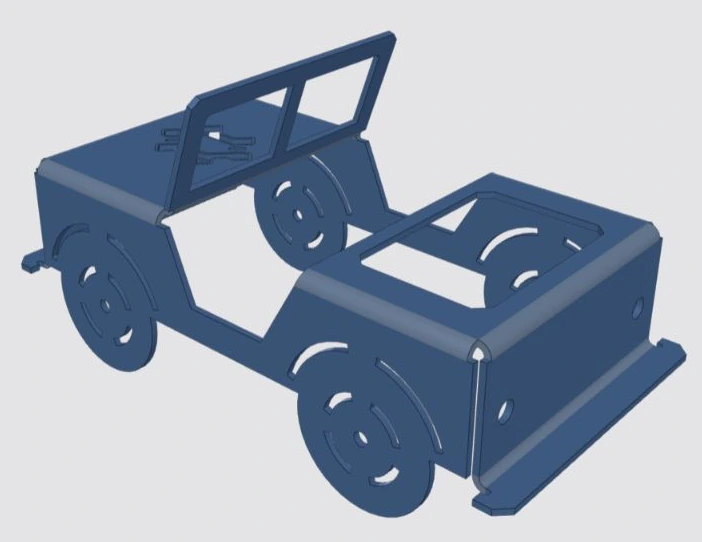
We tested it with Xeon Jeep.step: a compact sheet-metal body with wheel cutouts, narrow flanges, and nine recognized bends. It gives the tool a useful problem to investigate, and it gives designers a concrete way to learn the workflow.
SheetForm is currently running locally at Xeon. A public web release is planned. This article documents the build tested on September 13, 2026; the launch interface and available functions may evolve.
Start with the solid. Confirm the manufacturing context.
Select Upload STEP, use the file browser, or drop a STEP file into the workspace. Select the part in the left panel, then open Part in the feature rail. SheetForm reports dimensions, thickness, recognized features, and detection warnings from the uploaded geometry.
Our Jeep export returned a 6.000 × 3.094 × 2.992 in bounding box and 0.060 in / 1.52 mm sheet thickness. The panel also displayed an 8.203 × 6.497 in flat blank estimate. These are the current import’s reported values; the detection warning discussed below remains unresolved.
Confirm the Material dropdown against the intended stock. Our test used the selected Mild steel (CR, A1008) setting. Material is a selectable input here; the geometry read does not establish the alloy. The preview also offers Stainless 304, Aluminum 5052, and Galvanized steel.
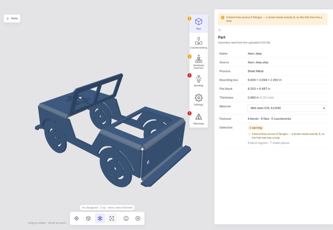
Drag the model to rotate it and scroll to zoom. The view toolbar includes reset and fit controls; the parts and details panels can be collapsed to give the geometry more space. Open Settings to find the inches and millimetres display options.
Inspect what the software recognized.
The Part panel reports 9 bends, 9 flats, and 0 countersinks. Its X-ray control ghosts the sheet and highlights recognized bend regions. That view helps connect the feature list to the physical surfaces you expect to form.
The Jeep also produces a fold-tree loop warning: the detected connections do not match the tree structure the tool expects. Treat that as an item to investigate in the recognition and source geometry before relying on the developed result. The presence of a rendered part does not resolve that warning.
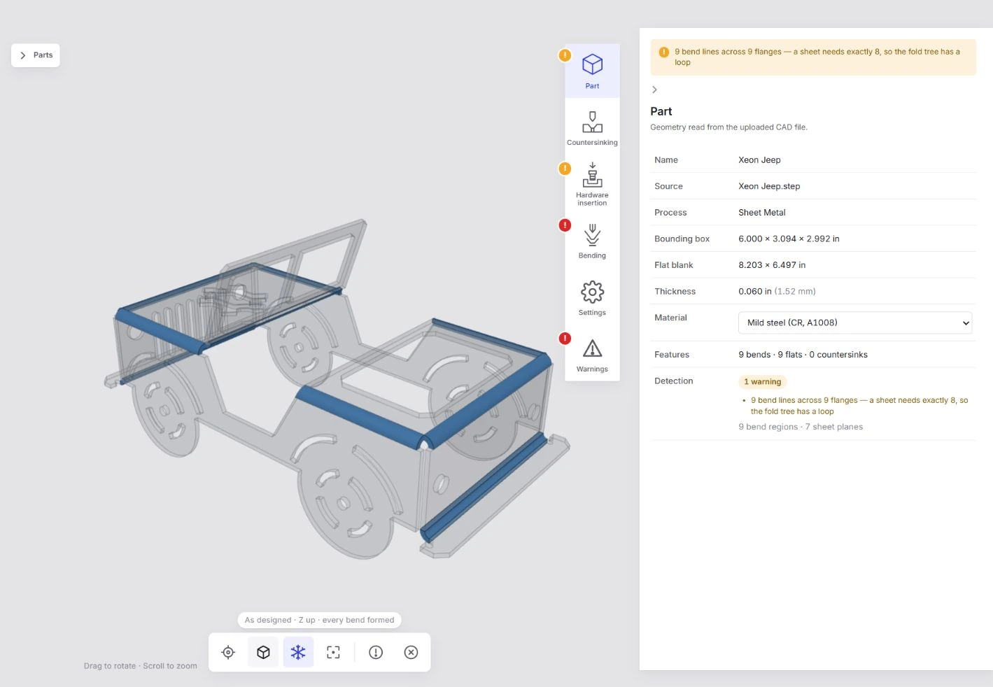
Open Bending and match B1–B9 to the model. In this import, B6 reads 70°; the other eight bends read 90°. Each displayed inside radius is 0.063 in. Expanding a bend row explains the angle, inside radius, and direction relative to the reference face.
These bend values are read from CAD and are read-only in the tested screen. For a geometry change, revise the source model and load the revised export. Bend numbers identify features; their numerical order does not prescribe the forming sequence.
Evaluate the bend against a specific setup.
Click a bend tag to seat that line in the press view. The Tooling and Machine controls govern what is shown. The In the press panel identifies the punch, die, stack length, minimum flange, and estimated air-bend force for the selected bend.
The displayed setup in our test used an OW300/S R1/86 H300 punch and an EV004 W12/30 R1 die with a 12 mm V opening. The interface provides Change controls for the punch and die, and a right-click tool shortcut in the press view. Check those selections against the tooling intended for the job before interpreting the result.
This matters immediately on the Jeep. With that die selected, the preview reports a 0.329 in minimum flange requirement. B8 has a shortest leg of 0.312 in, and B9 has 0.297 in. Both remain flagged for insufficient support at the die shoulder.
That is actionable design feedback: investigate the flange geometry and candidate tooling while the part is still in engineering. A different sequence alone does not add the missing support.
Nine bends. Seven strokes. A route you can examine.
Open the parts panel and select Simulate. SheetForm evaluates press cycles and returns a proposed sequence. Its playback controls let you move between strokes, play the progression, and change playback speed. Clicking a stroke seats the corresponding bend line; the sequence tags also expose drag-to-reorder controls.
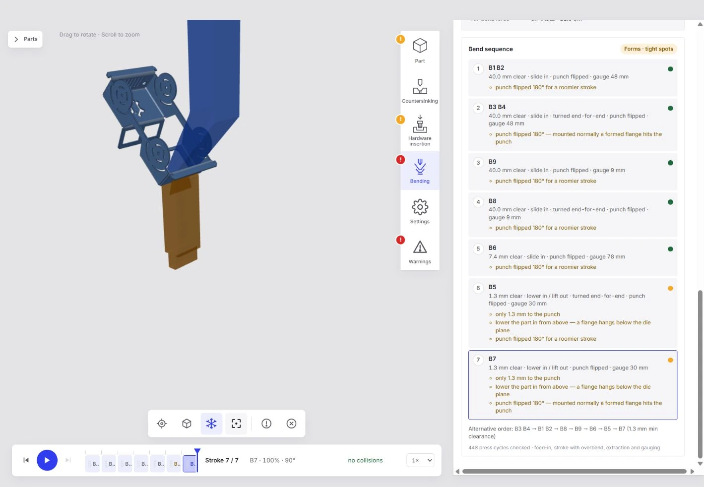
Before the search, the Jeep’s current order showed three collision zones. The completed run reported 448 press cycles checked, covering feed-in, the stroke with overbend, extraction, and gauging. It returned “Sequence OK · tight”: seven strokes, no reported collisions in that sequence, and 1.3 mm minimum modeled clearance.
Reported collision zones in the current order
No reported collisions · 1.3 mm minimum clearance
B1 and B2 share a stroke, as do B3 and B4. The remaining five bends form individually. The returned route moves B9 and B8 ahead of B6, B5, and B7, and supplies handling instructions for each operation.
| Stroke | Bend features | Part handling | Clearance |
|---|---|---|---|
| 1 | B1 + B2 | Slide in | 40.0 mm |
| 2 | B3 + B4 | Slide in · turned end-for-end | 40.0 mm |
| 3 | B9 | Slide in | 40.0 mm |
| 4 | B8 | Slide in · turned end-for-end | 40.0 mm |
| 5 | B6 | Slide in | 7.4 mm |
| 6 | B5 | Lower in / lift out · turned end-for-end | 1.3 mm · tight |
| 7 | B7 | Lower in / lift out | 1.3 mm · tight |
The route specifies a flipped punch for all seven strokes. At B5 and B7, it calls for lowering the part from above and lifting it out, because a flange hangs below the die plane. Both strokes report only 1.3 mm to the punch. Inspect those intermediate positions and handling notes alongside the clearance number.
The software also offered an alternative order with the same reported minimum clearance. This run establishes a candidate path within the preview’s model; it does not establish that the route is globally optimal.
Keep the unresolved items in the review.
Open Warnings after simulation. A successful sequence search answers a particular clearance question. It does not clear every other condition on the part.
With pull-through warnings enabled, the Jeep showed 12 flagged cutouts across four bends: two at B5, two at B6, one at B7, and seven at B9. The view marks affected geometry and provides warning badges to investigate. Hiding that overlay changes the displayed warnings; it does not change the geometry.
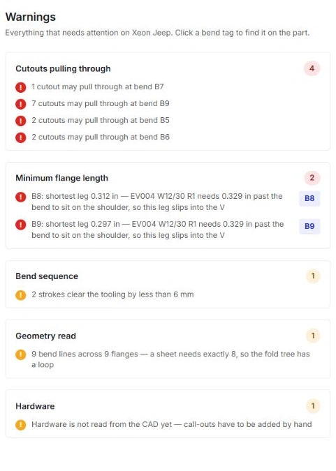
The two short-flange warnings, the two tight strokes, and the fold-tree warning also remained. The Hardware section states that hardware is not yet read automatically from CAD and that callouts must be added by hand.
Use those findings to structure the next revision: investigate recognition, assess flange support and openings near bends, confirm the setup, and rerun the changed part. Review the resulting geometry and process assumptions with the manufacturer before releasing production files. The specific thresholds shown here belong to this test and selected setup.
Move process feedback to the point of design.
For designers, the opportunity is earlier access to the consequences of a feature. A narrow lip, a decorative opening, or a flange near another wall can be examined in the context of an actual proposed bend sequence. The next CAD edit can respond to a visible constraint.
For engineers, SheetForm creates a common review surface. The conversation can name B9, its selected V opening, its shortest leg, and its position in the route. That is a more precise basis for comparing revisions than an isolated image of the completed part.
For a design-to-manufacturing handoff, the useful package includes the STEP revision, intended material and thickness, candidate tools, sequence, and unresolved checks. Keeping those assumptions together can reduce repeated clarification and reveal problems before they become shop-floor interruptions.
This is what makes the approach a potential game changer: designers can see more of the manufacturing problem while they still control the geometry. The Jeep run demonstrates that feedback mechanism. It does not measure time savings, cost reductions, or production yield; those outcomes need real jobs and measured results.
The next generation of sheet-metal design tools will make the route to the finished part visible from the beginning.
A documented preview, ready for the next iteration.
This walkthrough records a direct test of the local SheetForm Quote interface on September 13, 2026, using Xeon Jeep.step. Dimensions, warnings, tooling identifiers, cycle count, and clearances are the application’s reported results. Images are direct screenshots, cropped where stated and compressed for the web.
The Jeep remains an engineering test case with unresolved warnings. No physical bend trial or production release is claimed. The earlier Xeon Jeep CAD study documents its design story; the import and selected material recorded here define this particular simulation run.
SheetForm’s public web release is coming soon. This page will gain the launch link when it is available. In the meantime, use the walkthrough to understand the process and prepare a STEP model with a clear material, thickness, revision, and design requirements.
Follow the geometry into production.
Bring the model and the requirements.
Share the material, thickness, quantity, and critical features with your production files. SheetForm’s public launch link will be added when the tool goes live.
Start a Xeon quote ↗