Xeon NC / Sheet-metal Jeep / Design process
The shape survives the simplification.
The grille, open cabin, upright windshield, and circular wheel outlines do most of the work. Even without tires, axles, or a drivetrain, the silhouette reads immediately.
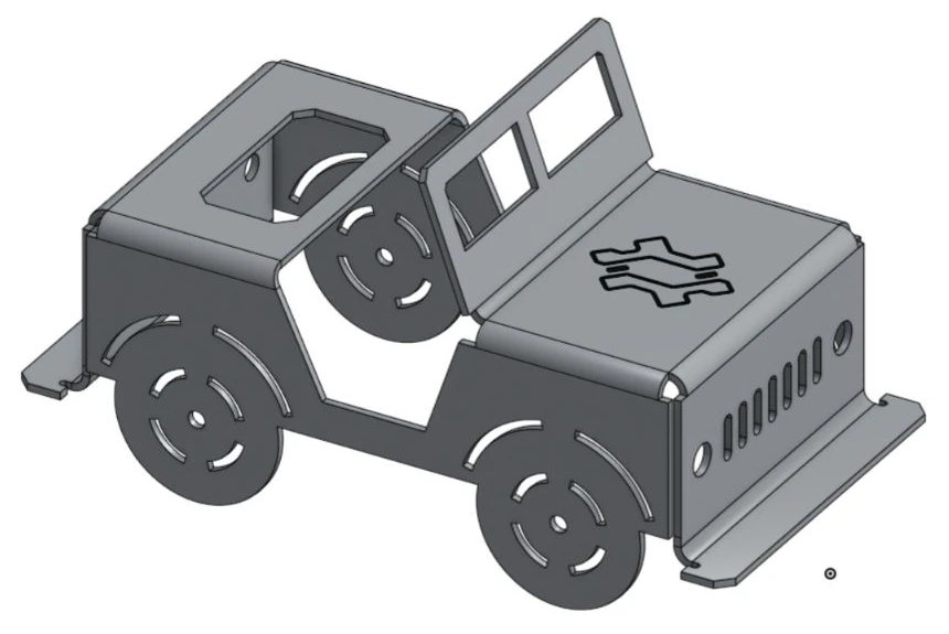
Our Onshape Jeep is a display model built around that recognition. The wheels are part of the side profiles. The headlights are openings. The body is a connected sheet-metal part whose bends establish the vehicle’s volume.
That makes it a useful design exercise. Every visual feature has to coexist with the material connecting it to the next one. An opening can suggest a wheel arch, but the remaining bridge must still carry the profile. A windshield can lean backward, but its base needs space for a real bend.
We inspected two saved Xeon documents for this article: Jeep, the nominal six-inch steel model, and Jeep bending, the eight-inch 5052 aluminum revision. The images are direct Onshape captures of these CAD models. The study documents their construction and differences; it does not report a completed physical build.
Build the character into the profile.
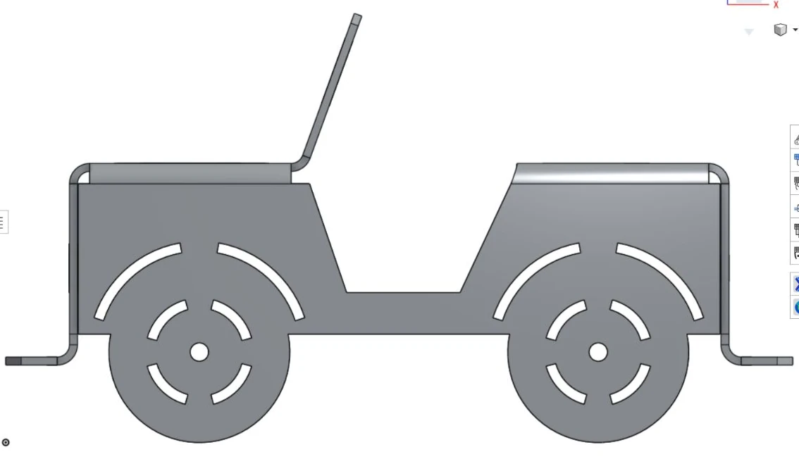
The side profile combines the hood line, low cabin opening, rear body, and two circular wheel forms. Four curved slots around each hub suggest a rim. Two larger arc slots describe the wheel arch while retaining connecting material between them.
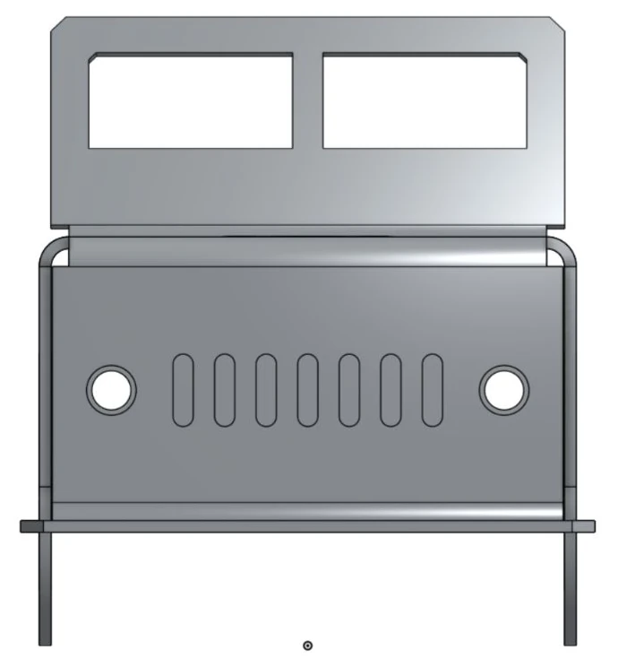
The front uses seven rounded slots and two circular headlight openings. A split windshield and the opening in the rear deck add recognizable detail without introducing separate glass or trim components.
These features are drawn as closed sketch boundaries in the saved FeatureScript. The script constructs panel surfaces for the hood, grille, bumpers, sides, rear deck, tailgate, and windshield. It joins those surfaces and passes the selected edges into Onshape’s sheet-metal operation. Thickness, bend radius, and K factor then become explicit model inputs.
The result shown in the Part Studio is one part. The manufacturing intent is carried by the connected blank, the selected bends, and the openings between adjacent regions.
A material change becomes a geometry change.
The second document goes beyond changing the material label. Its length input grows from six to eight inches, thickness increases, and the modeled inside bend radius doubles. The K factor also changes. Those choices alter the space available around every bend.
| Design input | Jeep | Jeep bending |
|---|---|---|
| Length input | 6 in | 8 in |
| Modeled material | Mild steel / nominal 16 gauge | 5052-H32 aluminum |
| Thickness | 0.060 in, as displayed | 0.080 in / 2.032 mm |
| Inside bend radius | 0.063 in, as displayed | 0.126 in / 3.2004 mm |
| K factor | 0.42 | 0.48 |
These are the feature inputs, not inspection results for finished parts. The part names preserve the nominal size and material identification. The actual formed envelope should be checked in the selected configuration before an export is released.
The revised source names an EV006 die and a 1 mm punch as its intended tooling reference. Its 0.126-inch inside radius is a separate modeled value. A tooling reference in source code records an assumption; confirming the resulting radius and developed length still requires the shop’s process data.
This is the useful lesson in the revision: changing stock affects more than mass or appearance. It changes the dimensional rules that the decorative features have to respect.
Reserve space for the bend.
The revised grille’s vertical slots are shorter relative to the panel. The windshield has more solid material below its window openings. The rear-deck opening is pulled inward from adjacent edges. The bumper regions are also deeper than a simple proportional enlargement of the original.
Those changes give the forming operation more uninterrupted material around its bend regions. In the saved source, the stated target is at least 12.5984 mm of straight clearance from bend tangency for the specified eight-inch configuration and tooling inputs. That is a project-specific design target. It needs to be checked against the regenerated geometry and the actual shop setup.
The underlying model remains editable, but parameter freedom is not proof that every combination is suitable for forming. Changing thickness, radius, or scale calls for a fresh clearance check. The saved source explicitly limits its clearance assumptions to the documented configuration.
For the general relationship between a cut feature and nearby forming, see our hole-to-bend distance guide. This small Jeep makes that relationship visible in a familiar object.
Read the flat and the formed part together.
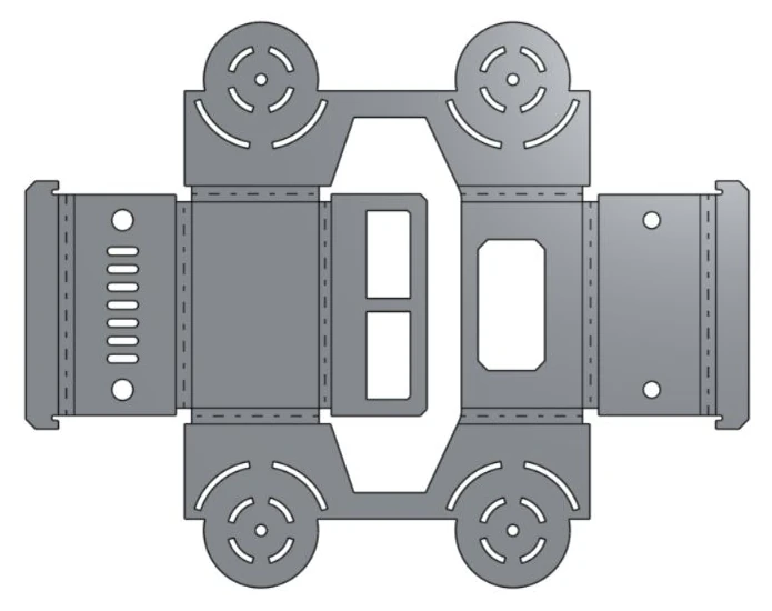
The flat view reveals how much of the model is already present before bending. The wheel shapes belong to the side panels, the windshield extends from the hood, and the grille and tailgate lead into the bumper regions. The three-dimensional identity emerges when these connected regions rotate into position.
Onshape’s bend table lists nine bends: eight at 90 degrees and one at 70 degrees. All nine display a 0.126-inch radius and a K factor of 0.48. Four additional joints are listed as rips. Those entries explain which boundaries fold and which remain separated in the sheet-metal model.
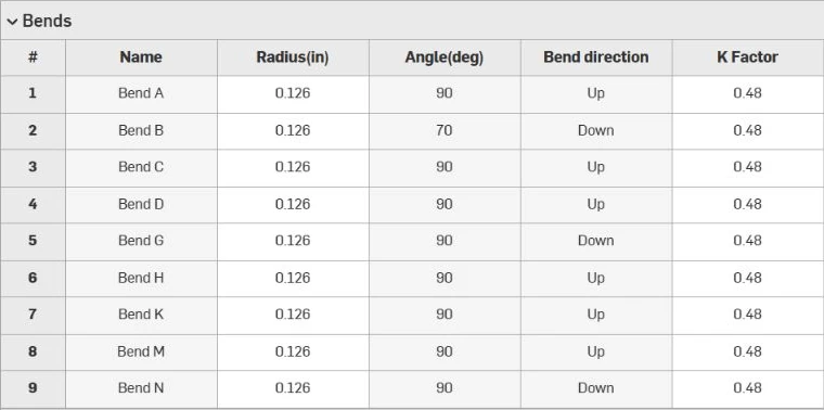
Onshape defines K factor as the fraction of material thickness locating the neutral axis. Alongside radius and angle, it controls the developed bend geometry. Here, 0.48 is the saved design input; the CAD capture does not establish a measured value for a particular machine and material lot.
A complete flat pattern is one part of the manufacturing definition. Bend sequence, tool access, backgauge references, and interference through intermediate positions still need to be established. The order of rows in a bend table should not be treated as a proven shop sequence.
Keep the marking operation explicit.
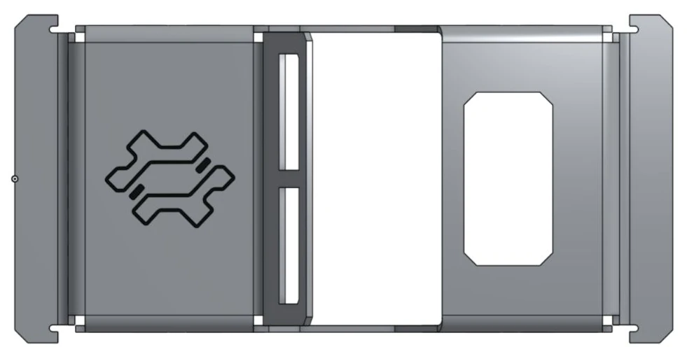
The saved feature tree places Hood logo etch after Finish sheet metal model. The logo-height input is 40 mm; the displayed etch-depth input is 0.001 inch. The custom feature subtracts a shallow contour from the hood and assigns the affected faces a dark appearance.
That modeling order matters. Onshape’s finish feature deactivates the sheet-metal model; subsequent solid operations do not update its flat pattern or bend table. The logo appearing on the formed hood therefore does not mean it has been included in the flat-pattern export.
The source calls for a separate etch file. A manufacturing release should identify the marking artwork, its position and orientation, and the intended marking process alongside the through-cut profile. The shallow CAD feature communicates intent; it does not specify a tested laser recipe or achieved engraving depth.
Leave a process another person can follow.
For this article, GPT-6 Astra helped inspect the saved FeatureScript, operate Onshape’s views, compare the two revisions, and turn the model evidence into an illustrated explanation. The progression presented here follows the saved designs; it is not a time-stamped account of their original creation.
The eight-inch document contains both a STEP tab and a flat-DXF tab whose filename identifies the 0.080-inch 5052 and EV006 configuration. Those names help trace intent. Before using either file, verify its units, revision, and geometry against the agreed model state, and include the separate marking definition.
The next physical checks are specific: confirm the selected stock and bend data, establish an accessible forming sequence, inspect the narrow wheel and window connections after cutting, and check the final shape against the intended dimensions. A first article would supply the evidence needed to refine the model’s assumptions.
Our layered skull study approaches the same design problem through many separate plate sections. The Jeep brings the form together through one connected sheet-metal part. Both make the construction visible enough to study.
The shape catches your attention. The flat pattern shows how it could be made.
Sources & capture notes.
Documented September 13, 2026. Images were captured directly in Onshape, cropped to remove surrounding interface, and compressed for the web. The existing feature inputs, source, native flat pattern, and bend table were inspected. Model geometry was not rewritten for this article. The sequence explains the saved construction and revisions, rather than reconstructing the original modeling session.
- Xeon — Jeep bending in Onshape
Primary evidence for the eight-inch aluminum configuration, native flat pattern, bend table, and feature history.
- Xeon — Jeep in Onshape
Primary evidence for the original nominal six-inch steel configuration. Existing document permissions apply to both model links.
- Onshape — Sheet Metal Model
Sheet-metal construction, bend inputs, K factor, and the relationship between selected edges and joints.
- Onshape — Finish Sheet Metal Model
Why solid operations after the finish feature do not change the native flat pattern.
- OpenAI — GPT-6 Astra
Official documentation for the model used to assist this inspection and article workflow.
See the decisions behind the shape.
Bring a shape worth building.
Include your model, material, thickness, finish, and forming requirements so the manufacturing plan starts with the right information.
Start a quote ↗