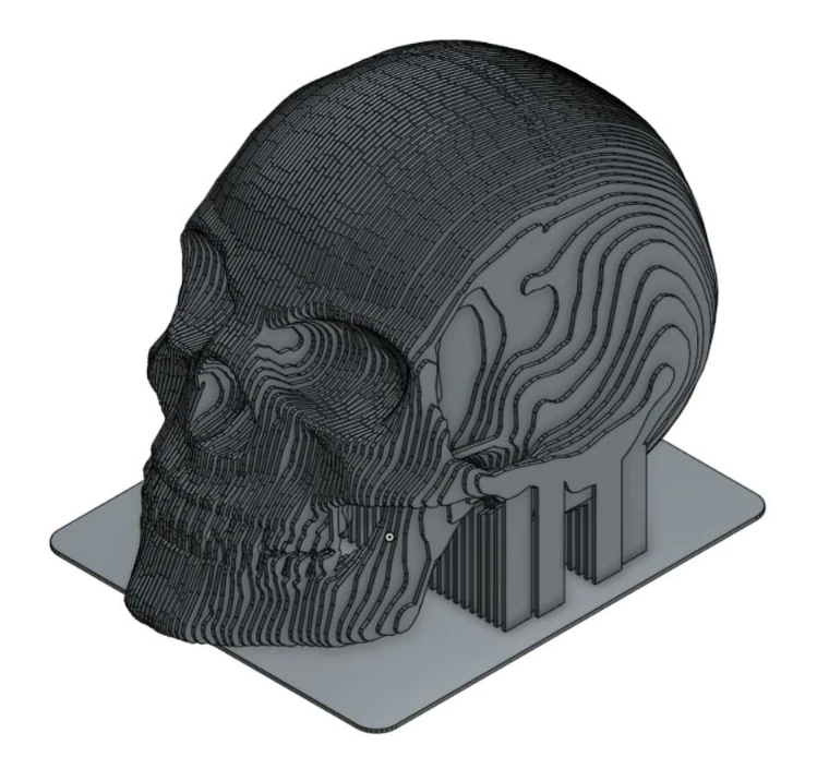
Xeon NC / Layered skull / Design process
The form appears between the plates.
From one angle, it is a skull. From another, it is a row of flat profiles. Move around it and the eye sockets, cheekbones, and jaw emerge from the changing depth of the edges.
That is the idea behind Xeon’s layered skull. A familiar organic form becomes a collection of constant-thickness parts, each positioned on a common base. The empty space is part of the design: it separates the sections while allowing the overall shape to remain legible.
We opened the saved Onshape model with GPT-6 Astra to inspect its construction, capture the views in this article, and trace the rules that connect its dimensions. The current configuration contains 73 skull plates and one base. Its skull-height input is 12 inches; each plate is 0.100 inch thick. The material property in the model is mild steel.
This is a CAD design study. The images show modeled parts, and the process below follows the saved generator. A physical build would add the evidence that CAD cannot supply: cut-edge quality, fit, handling, and stability.
Give the shape a manufacturing language.
The saved source credits Vladimir Petkovic’s ScatteringSkull reference in the Khronos sample-asset collection, which is listed under CC0 1.0. That reference supplies the anatomical form. The plate construction is a separate engineering interpretation.
Inside the Onshape Feature Studio, the shape is stored as a symmetric bank of section profiles. The source describes 81 lateral stations per half skull. At each selected plate position, the generator chooses the nearest stored station and draws its closed outline. It then extrudes the profile to the specified stock thickness.
Look at the isolated center plate below. The broad head profile, narrow connection toward the jaw, and two legs belong to one part. Connected bridges retain material that would otherwise become separate pieces when a three-dimensional form is divided into sections. These narrow regions deserve particular attention during a cutting and handling review.
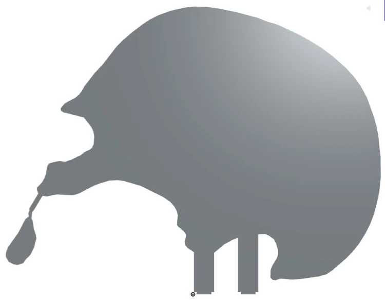
The plates are modeled as straight extrusions. This construction requires no modeled bends, so the flat layout is a rearrangement of the parts rather than a bend-unfold operation. The order of those parts matters as much as their outlines.
Let the stock set the rhythm.
Scale, stock thickness, and spacing are coupled. Keep the skull width fixed and thicker stock leaves room for fewer plates. Increase the skull size while retaining the same stock and more sections can fit across it.
The generator first calculates a plate count from the available width, thickness, and requested minimum gap. It reduces an even result to an odd number, retaining a center plate, and bounds the result between 5 and 81. It then distributes the plate centers evenly across the width. The resulting gap can therefore be slightly larger than the requested minimum.
| Quantity | Value | What it controls |
|---|---|---|
| Skull-height input | 12 in / 304.8 mm | Reference shape scale; excludes the base and stand-off |
| Plate thickness | 0.100 in / 2.54 mm | Extrusion thickness and slot-width calculation |
| Minimum plate gap | 0.030 in / 0.762 mm | Input used to select the plate count |
| Skull plate count | 73 | One center plate and 36 positions to each side |
| Plate-center pitch | 3.3838 mm | Calculated uniform spacing |
| Actual plate gap | 0.8438 mm | Pitch minus 2.54 mm stock thickness |
For this configuration, the nominal outside width across the plates is 246.1748 mm. With N plates, width W, and thickness t, the center pitch is (W − t) / (N − 1). Subtract t once more to obtain the clear gap between adjacent plates.
Change the scale. Watch the count.
Stock stays at 0.100 in and the minimum gap at 0.030 in. This calculation follows the saved feature; it does not change Onshape or the photographed 12-inch model.
At 6 inches, the same rule produces 37 plates. The visual bars indicate count only; they are not a geometric skull preview.
The base carries the assembly logic.
A collection of profiles needs a way to become a repeatable arrangement. Each plate in this model has two locating tabs. The base uses the same calculated plate positions and tab-center data to generate two corresponding slots per plate: 146 slots for 73 plates.
Adjacent plates alternate between two tab patterns. Viewed from above, that alternation produces four staggered slot rows. It spreads the openings along the base instead of collecting every tab into the same two rows. The remaining material between openings still needs to be reviewed for the selected process and stock.
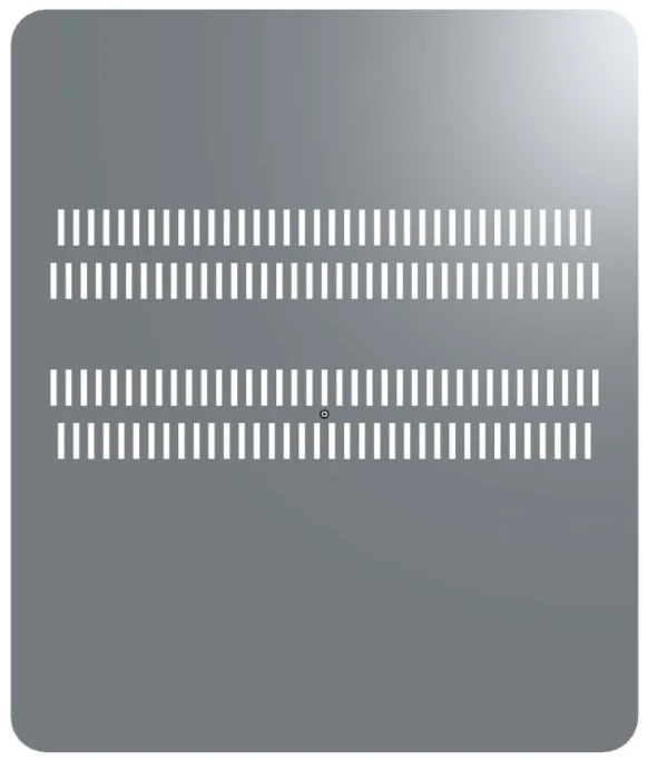
The slot-clearance input is 0.006 inch total added width and length, equivalent to 0.1524 mm. With 2.54 mm stock, the modeled slot width is therefore 2.6924 mm. At the 12-inch scale, the 16 mm tab length receives a 16.1524 mm slot. The allowance is total, not 0.006 inch on each side.
That number is a design input, not a measured fit result. Actual stock thickness, cut geometry, burrs, and any finish must fit within the intended assembly allowance. A small tab-and-slot coupon made from the chosen stock would test the relationship before committing to the complete set.
The two tabs locate each plate in the base plane. Retention, resistance to lifting, and stability under handling remain separate design decisions. The pictured model does not demonstrate a tested fastening or welding method.
Resolve the sculpture into individual parts.
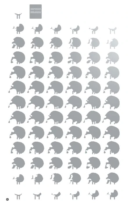
Switching Layout for cutting on moves each plate onto a common horizontal plane. The same profile, thickness, and part identity are retained. The base moves into the layout as well.
The saved feature uses a spaced, six-column grid. That is useful for inspecting the collection and keeping the profiles separate. It is not an optimized nest or a machine program: sheet boundaries, material yield, lead-ins, cutting order, and machine-specific allowances are not defined by this view.
The parts list names the skull sections P01 through P73. Those names provide a starting point for an assembly map. A production package should preserve the relationship between the part identifier, its cut profile, and its position on the base. CAD names alone do not create physical marks on the cut parts.
Onshape supports exporting planar faces and sketches as DXF/DWG. Confirm the export units, scale, and complete part set against the intended configuration. The document also contains a DXF tab whose filename identifies a 6-inch skull, while the current model is set to 12 inches. A saved export should always be checked against the current design state.
Make the decisions inspectable.
The interesting use of AI here is the connection between design intent and an inspectable model. An organic reference supplies the shape. The saved FeatureScript supplies explicit rules for selecting sections, assigning thickness, distributing plates, creating tabs, and generating the matching base.
For this field note, GPT-6 Astra helped inspect that saved system, operate the Onshape views, and translate the source into an illustrated explanation. OpenAI describes Astra as supporting complex reasoning, coding, computer use, research, and document creation. This article documents one workflow; it does not establish a manufacturing benchmark or a build-time claim.
Onshape’s Feature Studio makes the construction logic available alongside the geometry. Open the Layered skull feature and the exposed inputs are immediately visible. Read the source and the plate-count rule, alternating tab patterns, and total slot allowance can be traced directly.
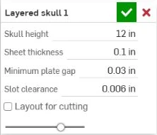
That is a useful standard for AI-assisted engineering work: the result should leave behind geometry and decisions that another person can inspect. A convincing image starts the conversation. The part definitions carry it forward.
The next proof is physical.
The skull makes a strong visual object because its construction stays visible. Every plate announces the manufacturing method. Every gap contributes to the surface. The base records where each section belongs.
Before turning this study into a cut set, the next work is concrete:
- Measure the selected stock and test the proposed tab-and-slot allowance on a small coupon.
- Review thin bridges, narrow remnants, internal openings, and accessible edges against the cutting and deburring process.
- Define plate order, orientation, physical identification, retention, and a handling-stability check.
- Export the agreed size and revision; verify units and a known dimension after import into the cutting workflow.
Those steps connect the model to material. For the broader fit problem, read Why good parts don’t fit. For export control, continue with The second order is a different engineering problem.
The skull is the object. The repeatable relationship between shape, stock, and assembly is the work.
Sources & capture notes.
The images are direct Onshape viewport captures, cropped to remove surrounding interface where appropriate and compressed for the web. They document the saved 12-inch model, isolated components, and a temporary cutting-layout preview. The source feature was inspected without rewriting it. The step sequence is an explanation of the saved construction logic, not a time-stamped record of the original modeling session.
- Xeon — Skull in Onshape
Primary source for the model, exposed feature inputs, part count, and CAD captures. Document access follows its existing sharing permissions.
- Khronos — ScatteringSkull
Reference model credited to Vladimir Petkovic; the asset’s README lists CC0 1.0.
- Onshape — Feature Studios
How FeatureScript defines custom parametric features inside an Onshape document.
- Onshape — Exporting files
Supported export routes for model parts, planar faces, and sketches.
- OpenAI — GPT-6 Astra
Official model documentation supporting the description of Astra’s reasoning, coding, and computer-use capabilities.
Carry the model into the next decision.
Bring a shape worth building.
Include the intended material, thickness, finish, and assembly requirements with your model or cut profiles.
Start a quote ↗