Minimum laser-cut
hole size.
Why the pierce and lead-in need room—and how a laser-marked center lets you drill a smaller hole after cutting.
Use the Min Recommended Hole Size and Min Hole Size on the material page for your alloy, thickness, and finish. If your hole is too small to cut reliably, plan a laser-marked center and drill the final hole afterward.
Two limits.
Two different decisions.
A small circle can be perfectly valid in CAD and still be difficult to produce cleanly with a sheet-metal laser. The minimum is a process limit, not simply the diameter of the focused beam.
Our material pages list two hole sizes. Min Recommended Hole Size is the preferred design threshold for better hole quality. Min Hole Size is the smaller listed laser-cut limit. A hole between those values may be cut, but it can have more taper or roughness. Neither value is a guarantee of a precision fit.
| Material / thickness / finish | Min Recommended Hole Size | Min Hole Size |
|---|---|---|
| 0.063″ 5052-H32 aluminumMill | 0.032″ | 0.016″ |
| 0.188″ 5052-H32 aluminumMill | 0.094″ | 0.047″ |
| 0.625″ 6061-T6 aluminumMill | 0.375″ | 0.188″ |
| 0.625″ A36 steelMill Scale | 0.625″ | 0.313″ |
Catalog reference checked 2026-09-22. These are selected examples, not a rule for every alloy or thickness. Always check the current material page for the stock you order.
For example, a 0.025″ hole in 0.063″ 5052-H32 mill-finish aluminum falls between the 0.016″ minimum and the 0.032″ recommendation. It needs a quality and fit review; it is not automatically below the cut limit. A 0.012″ hole in that same stock falls below the listed minimum and should be planned for another process.
- At or above recommended
- Design for laser cutting, then check the drawing tolerance and the function of the hole. Precision bores may still need machining.
- Between minimum and recommended
- Review the expected edge quality. A laser-cut hole may be suitable for clearance, while a controlled fit may need drilling or reaming.
- Below the listed minimum
- Use the mark-and-drill workflow, revise the design, or request a secondary-operation quote. Do not assume the small circle will arrive as a finished laser-cut hole.
The circle is only
part of the toolpath.
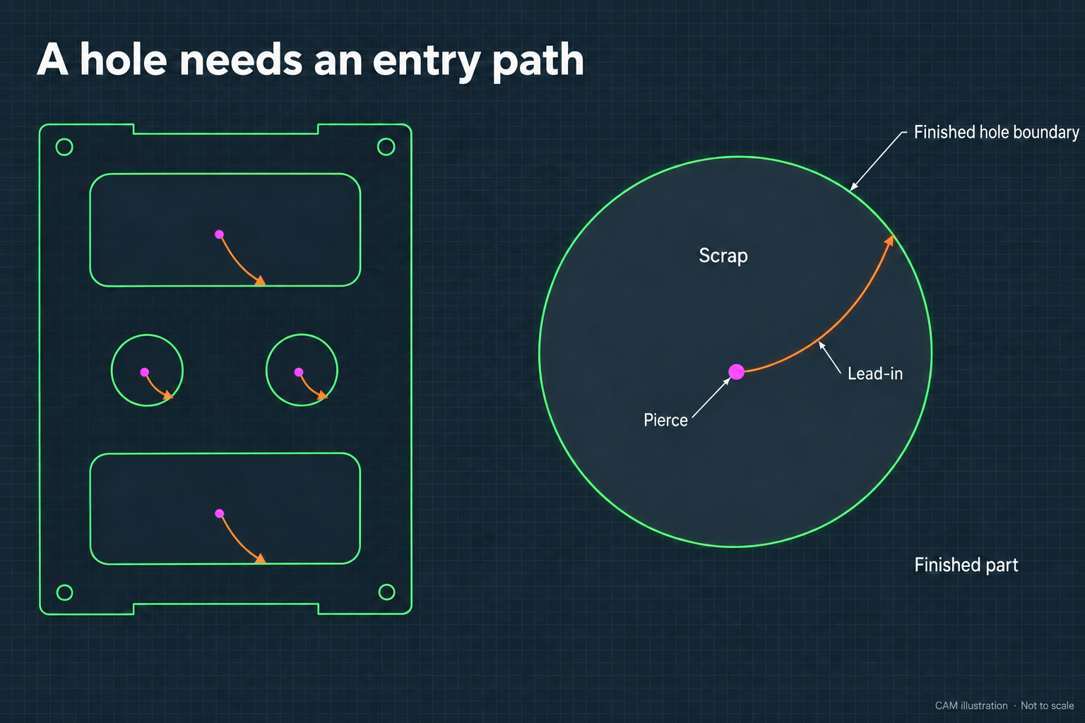
Your CAD file describes the finished part. CAM software adds the manufacturing instructions: where to pierce, how to enter each contour, which side of the line to cut, and what sequence to follow. Laser CAM uses material- and machine-specific process settings, including piercing and lead-in strategies. Lantek’s laser CAM overview describes these programming controls.
Pierce through the scrap
For a typical internal contour, the laser first makes a through-opening in the material that will be removed. Piercing is a local start event; it can leave a crater, spatter, or a disturbed edge around that starting point.
Lead into the contour
The beam moves from the pierce location toward the hole boundary. This entry path, called the lead-in, helps keep the initial pierce away from the finished edge. Its shape and length depend on the process and available space.
Cut the hole boundary
The head follows the programmed contour. CAM accounts for the material removed by the cut—the kerf—so the intended boundary is left on the part. The interior material is scrap. The diagrams simplify this by drawing the entry directly to the nominal boundary.
A large cutout has plenty of scrap area for its entry. A tiny hole gives the programmer a much smaller area in which to fit the pierce and lead-in. Starting farther outside the circle would damage material that belongs to your finished part.
Less room to enter.
Less margin for a clean edge.
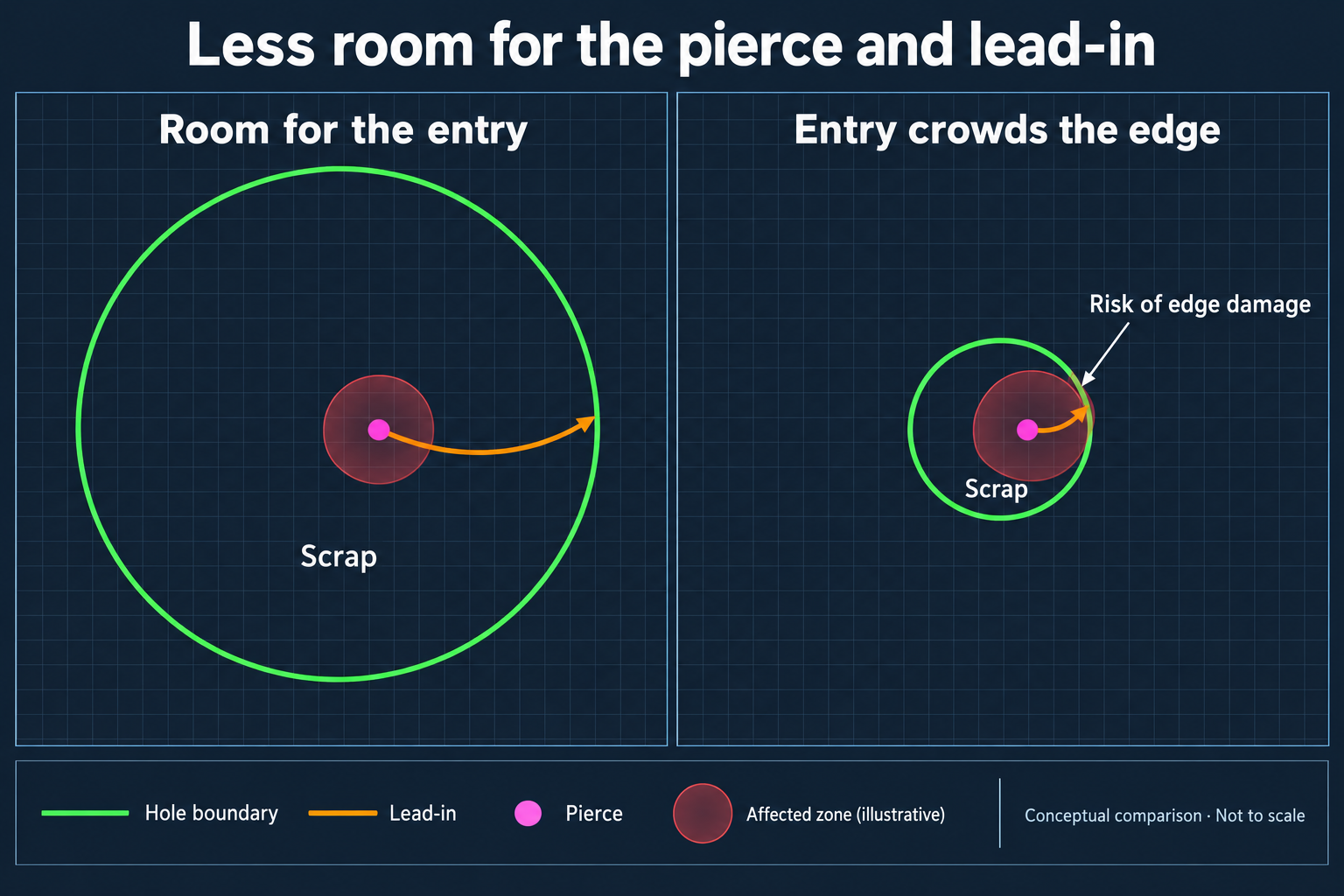
The pierce and lead-in are important reasons for a minimum hole size, but they are not the only ones. The laser must also maintain a stable cut around a tight curve and clear molten material through a narrow opening.
During laser cutting, the beam melts or vaporizes material and assist gas clears material from the kerf. Focus, nozzle and gas flow, thickness, and cutting speed influence the result. A small beam alone does not guarantee a clean small hole. TRUMPF’s laser-cutting explanation covers these process relationships.
As the diameter shrinks, heat is concentrated around a shorter contour and there is less room to separate the start event from the finished wall. Depending on the stock and settings, a hole below the recommendation may show:
- An entry witness or divot: the start leaves a visible defect in the hole wall.
- Taper: the opening measures differently at the top and bottom of the sheet.
- Dross or a rough edge: resolidified material remains at the cut.
- Poor size or roundness: the opening does not provide the clearance or fit shown in the drawing.
These are risks, not defects that occur in every small hole. Increasing power or overriding a CAM check is not a reliable substitute for an appropriate process. That is why we use stock-specific catalog values instead of one universal diameter-to-thickness rule.
We mark the location.
You drill the final size.
When a hole is below the listed laser-cut minimum, the mark-and-drill route keeps the intended location without forcing an unreliable circular cut. We laser-mark the hole center so you can locate it and drill the finished hole after receiving the part. For holes between the minimum and recommended sizes, this can also be a useful option when the final fit matters.
Identify these holes in your drawing and order notes so the marking plan is clear before production. Keep the finished hole diameter and location in the design; do not enlarge the hole simply to get through a cutting check.
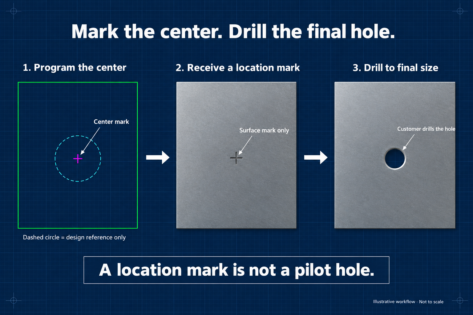
It does not remove the full hole diameter or guarantee that a drill will locate itself. Drilling, deburring, and checking the final hole are customer operations unless included separately in your quote.
Plan the drilling operation
Secure and support the part with suitable workholding. Use the mark with your drawing datums to locate the hole; use an appropriate spotting or center-punch operation if the drilling setup requires it. Select tooling and a drilling process suited to the alloy, hardness, thickness, and required accuracy. Some materials require a machine-shop setup.
After drilling, deburr and inspect the diameter and position. Close-tolerance pin holes, bearing fits, and other precision features may require reaming or machining. Specify those requirements before ordering.
Think about access and finishing
A hole that is easy to reach in a flat blank may be difficult to drill after bending. Coatings can obscure a light mark, and drilling after finishing exposes a fresh edge. Coordinate marking, bending, drilling, and finishing so the part remains accessible and the final surface meets your requirements.
Call out the final hole.
Identify the center mark.
Supply the final nominal hole geometry in your model or drawing, and explicitly identify which locations are to be marked instead of cut. Use the agreed marking-layer or file convention; an unexplained cross or tiny circle on a cutting layer can be interpreted as geometry to cut.
Dimension the center from drawing datums, show the final diameter and quantity, identify the marked face where it matters, and state who performs the drilling. An example callout is:
LASER MARK CENTER ONLY.
DRILL Ø[FINAL DIAMETER] THRU BY CUSTOMER.
[QUANTITY] PLACES — LOCATE FROM DATUMS [A / B].
DO NOT LASER CUT THESE HOLES.
Do not add your own pierce points or lead-ins to the finished-part cutting geometry. We program those in CAM for the selected material and process. If you need a drilled or reamed hole supplied complete, request that operation and its tolerance in a custom quote.
Before you upload
Check your exact stock’s two hole-size limits, identify any mark-only locations, and include the final drilling requirements.
Further reading
Xeon laser-cutting design guide · CAD file preparation · TRUMPF: laser-cutting process · Lantek: laser CAM programming
Illustrations created for this guide to explain the process. They are not machine-program screenshots, qualified toolpaths, or dimensional specifications.