Making a part is only the beginning.
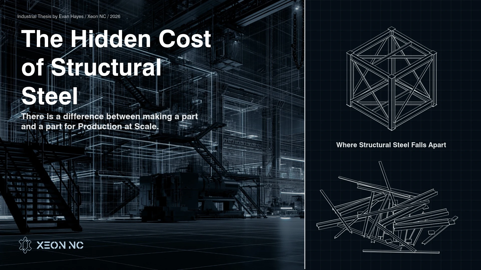
There is a difference between making a part and manufacturing a product.
A single component can be machined perfectly. A weldment can pass inspection. A bracket can be made to print. None of that necessarily means the product will be easy to manufacture at scale.
Earlier in my career, I worked as an applications engineer manufacturing products composed of dozens—and sometimes hundreds—of individual components. These were not isolated prototype parts. They were assemblies containing laser-cut sheet metal, formed parts, machined components, saw-cut structural steel, welded assemblies, hardware, paint, powder coat, and final mechanical assembly.
That experience changed how I think about tolerance. Not tolerance as a number printed next to a dimension. Tolerance as a system.
Because once enough parts have to locate, align, weld, bolt together, and repeat across production quantities, the nominal geometry of a component becomes far less important than the repeatability of the process that created it.
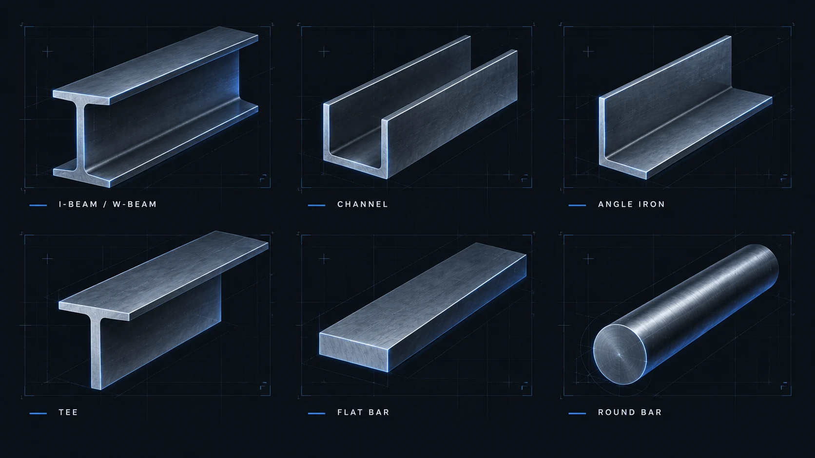
One project made that particularly clear. The customer had deliberately designed much of the product around common structural steel shapes: angle iron, channel, I-beam, and similar sections. The reasoning was logical.
Structural steel is widely available. Nearly every fabrication shop owns a saw. Many shops can drill or machine it. Tube lasers and other automated equipment can process structural profiles. The customer wanted the product to be manufacturable by a broad supplier base without requiring highly specialized equipment.
On paper, this should have reduced manufacturing complexity. In practice, we discovered almost the opposite. The structural components became some of the most difficult parts of the product to manufacture. The problem was not cutting them.
The problem was geometry.
Nominal Geometry Is Not Actual Geometry
A CAD model presents an ideal world. A 3-inch channel is straight. An angle is square. A tube has perfectly controlled faces. An I-beam exists exactly where the coordinate system says it exists. Manufacturing does not receive the CAD model.
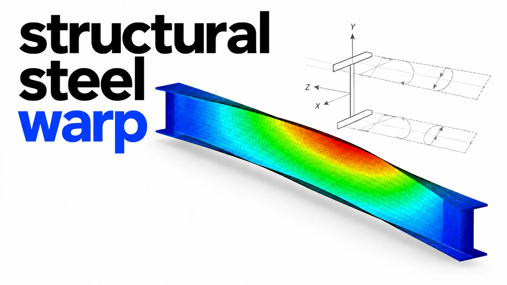
Manufacturing receives steel. Rolled structural material is produced to standards that are entirely appropriate for its intended applications. But those standards allow variation in straightness, twist, flange geometry, wall position, section dimensions, and other characteristics.
That variation may be irrelevant when constructing a building. It becomes extremely relevant when the section becomes part of a precision mechanical assembly. A twelve-foot structural member can be perfectly acceptable according to its material specification and still contain enough bow or twist to create substantial problems downstream.
Now put that member into a machining fixture. Which surface is the datum? Clamp the center and the ends may move. Clamp the ends and the center may move. Force the material flat and you may simply be storing elastic energy in the part until the clamps are released.
Machine features into that condition and the relationship between those features can change when the part returns toward its natural shape. The machining center is not necessarily the source of the error. The raw material is.
Cutting Accuracy Does Not Correct Material Geometry
This distinction becomes important when discussing automation. A tube laser can locate and cut features into a structural section with extraordinary precision. That does not automatically make the finished component geometrically precise. The machine controls the toolpath.
It does not necessarily control the straightness of the material entering the machine. If a channel is bowed before processing, precisely cutting a hole into the channel does not make the channel straight. You now have a very accurately positioned hole on a potentially non-ideal piece of material.
That may be completely acceptable for some applications. For assemblies requiring multiple components to locate against one another, however, it can create an entirely different problem. The process is accurate. The product is still difficult to assemble.
Those are not contradictory statements.
Fit-Up Is Manufacturing
This was one of the more important lessons from that project. We spent significant amounts of time fitting structural components before welding. A component would be slightly bowed. Another would have some twist. A third would sit slightly differently in the fixture.
Individually, none of these deviations seemed particularly dramatic. Together, they became an assembly problem. Operators had to clamp components into position. Pull structures square. Push members against fixtures. Check diagonals. Reposition parts. Tack weld. Measure again.
Break a tack occasionally. Pull the assembly back into position. Then weld while attempting to control additional distortion created by the welding process itself. The drawing might specify the same final dimensions every time. The path required to reach those dimensions was different for almost every assembly.
That distinction matters enormously in production.
Manual correction is a manufacturing process.
It consumes labor. It consumes machine capacity. It requires skilled judgment. It introduces operator-to-operator variability. And unlike cutting time or machining cycle time, it can be difficult to predict. A weldment that takes twenty minutes to fit today may take forty minutes tomorrow because the next pieces of incoming structural steel happen to contain a different combination of bow and twist.
When producing one assembly, this can be inconvenient. When producing hundreds, it becomes a production-system problem.
Sheet Metal Changes Where the Geometry Comes From
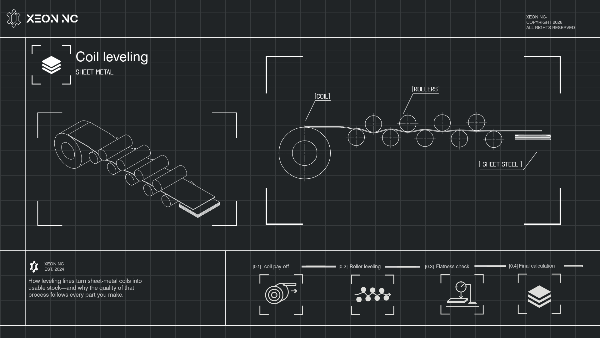
This is where laser-cut and formed sheet metal becomes interesting. Suppose we need a channel-shaped component. There are at least two fundamentally different ways to manufacture it. We can purchase a rolled structural channel and cut it to length.
Or we can begin with flat sheet, laser cut the developed profile, and form the channel on a press brake. Both parts may look nearly identical in the final assembly. But they are created through very different geometric systems.
With the structural section, much of the finished geometry is inherited from the upstream rolling process. With a laser-cut and formed component, far more of the geometry is defined directly by the manufacturing process used to create the part.
The laser defines the profile. It defines hole locations. It defines slots. It defines tabs. It defines reliefs. It defines features relative to a common two-dimensional coordinate system. The press brake then transforms that controlled flat geometry into three-dimensional geometry.
That transformation introduces its own variables—material thickness, grain direction, tensile properties, tooling, bend radius, springback, bend deduction, machine accuracy—but critically, those variables can be modeled and controlled. Modern CNC press brakes make this even more powerful.
The objective is not that every bent sheet-metal part is inherently perfect. It is that the process can be made repeatable. And repeatability is what allows manufacturing to scale.
One Blank Can Replace an Assembly
There is another advantage. Sheet-metal design allows geometry to be consolidated. Consider a fabricated channel requiring:
- two side walls,
- a bottom plate,
- several mounting holes,
- locating features,
- and attachment points for another component.
A traditional fabricated design might require multiple pieces to be cut, located in a fixture, clamped, and welded together. A formed sheet-metal design may place all of those features into a single flat blank. The laser cuts the entire geometry in one coordinate system.
The brake establishes the walls. What previously required several components and several opportunities for positional error becomes one component. That is not merely part consolidation. It is tolerance-chain reduction. Every interface removed from a product removes another opportunity for dimensional variation.
Every weld eliminated removes another source of heat distortion. Every component eliminated removes another item that must be purchased, handled, identified, staged, located, inspected, and assembled. That is how a seemingly more sophisticated manufacturing process can ultimately produce a simpler product.
The Real Enemy Is Accumulated Variation
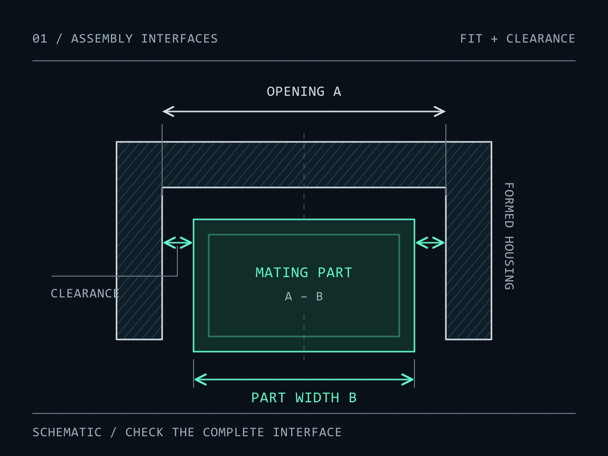
Engineers frequently evaluate tolerances component by component. Production exposes the interactions between them. Imagine an assembly with several structural members. One contains slight bow. Another has slight twist. A machined hole pattern is slightly displaced because the material did not sit identically in the fixture.
A welded bracket pulls several thousandths during cooling. A powder-coated mating component gains thickness. A fastener has normal clearance in its hole. No single condition necessarily violates the drawing. Yet the assembly can still become difficult to build.
This is tolerance stack-up in its practical form. Not simply an equation on a drawing. It is accumulated variation moving through the manufacturing system. At sufficient scale, tiny inconsistencies become labor. And labor becomes cost.
Welding Amplifies the Problem
Welding structural material adds another layer of uncertainty. A welded assembly contains significant thermal gradients. Material expands. Material contracts. Residual stresses redistribute. Long members move. The more effort required to force an already-variable structural component into position before welding, the more complex the distortion problem can become afterward.
Fixtures help. Weld sequencing helps. Balanced welds help. Experienced welders help. None of those are free. A well-designed formed component can often move geometry upstream—away from welding and into cutting and bending. Instead of using a welder to determine where two pieces belong, the part itself can define the location.
Tabs can locate into slots. Edges can register against formed surfaces. Holes can originate from the same laser-cut pattern. Bends can create features that previously required welded components. The operator is no longer manufacturing the geometry manually.
The geometry is encoded into the part. That is a fundamentally different production strategy.
Design the Part to Assemble Itself
This is one of the strongest arguments for modern sheet-metal fabrication. A good sheet-metal design does not simply make the component easier to manufacture. It makes the assembly easier to manufacture. Slots can constrain translation.
Tabs can establish location. Formed flanges can establish orientation. Shared laser-cut features can preserve relationships between components. Self-fixturing geometry can reduce the amount of interpretation required during welding. Instead of handing a welder several pieces of steel and a drawing and asking the welder to reproduce the CAD model, the components can physically constrain one another toward the intended geometry.
The welder's primary job becomes joining the assembly. Not reconstructing its dimensional architecture. That difference matters. Skilled labor should be used where skill creates value—not to repeatedly compensate for variation that could have been removed through design.
Structural Steel Still Has a Place
None of this means structural steel is a poor manufacturing material. There are applications where it is unquestionably the correct choice. Long spans. Heavy load-bearing members. Large cross sections. Extremely thick sections. Products where structural profiles closely match the required final geometry.
Low-precision assemblies where straightness and twist have little effect on function. Products where the cost of forming an equivalent section would outweigh the downstream advantages. There are also situations where tube lasers make structural profiles extraordinarily efficient.
The point is not that sheet metal should replace every tube, angle, or channel. The point is that engineers should not assume that an off-the-shelf structural shape is automatically the lower-cost manufacturing solution simply because the raw material already resembles the final part.
Raw-material cost is only one component of manufacturing cost. The relevant question is:
What does this material choice do to the entire production system?
Measure the Process, Not the Piece
Consider two designs. Design A uses inexpensive structural channel. Design B uses a laser-cut and formed sheet-metal channel that costs more to process initially. At the purchasing level, Design A may appear cheaper. But now measure everything downstream.
How long does the material take to inspect? How difficult is it to fixture? How much variation exists between pieces? How many machining setups are required? How much time does weld fit-up consume? How much rework occurs?
How complicated must the fixture become? How many operators need to understand the adjustment process? How much work-in-process accumulates around welding? How predictable is the cycle time? How easily can another machine, operator, or facility reproduce the result?
That is the actual cost model. Manufacturing cost is not the price of the blank. It is the cost of converting material into a conforming product.
At Scale, Predictability Becomes a Feature
This is ultimately what changed my perspective. When building larger products, manufacturing engineering stops being exclusively about whether a process can make a component. Most capable fabrication shops can make extraordinarily difficult parts. The more important question is whether the process can make that component repeatedly, predictably, and with minimal intervention.
There is a major difference between:
We can make this.
and:
We can make this the same way every time.
The second statement is what production requires.
A process that depends on an experienced fabricator seeing a bowed member, understanding where to clamp it, knowing how far to pull it, predicting how the weld will move it, and compensating accordingly can produce excellent work.
But that knowledge lives partly inside the operator. A process built around controlled laser-cut geometry, defined bend locations, repeatable tooling, locating features, and deterministic assembly moves more of that knowledge into the product and the manufacturing system itself.
That makes the process easier to scale.
Geometry Is a Manufacturing Decision
The lesson I took from that experience was not that structural steel is bad. It was that geometry has a supply chain. Every manufacturing method inherits variation from the process before it. Rolled sections inherit the characteristics of rolling.
Saw-cut parts inherit the geometry of the incoming section. Machined structural components inherit both the raw-material geometry and the machining setup. Weldments inherit the variation of their components plus the effects of fit-up and heat.
Laser-cut and formed parts have their own constraints, but they give engineers a powerful ability to establish much of the product geometry from a controlled digital definition. For many products, that matters more than the apparent simplicity of buying a pre-existing structural shape.
When I look at a component today—particularly one that will eventually become part of a larger mechanical assembly—I do not only ask:
What is the easiest way to make this part?
I ask:
What is the easiest way to repeatedly manufacture the complete product?
Those are very different questions. And in more cases than people realize, the answer begins with a flat sheet of metal.