Design feedback in seconds, not days.
Most DFM feedback arrives after you send a file and wait for someone to review it. SheetForm gives you the same answers while the model is still open in CAD: upload a STEP, and it reads the part, forms it on the tooling we run, and lists what to fix.
It is built for engineers. Every finding names the bend it belongs to, measures the problem (how close the cutout is, how short the leg is, how much clearance the punch has), and says what to change. It runs entirely in the browser, so your file stays on your computer.
Open SheetForm in another tab and follow along with your own part.
Open SheetForm →A desktop browser and a STEP file.
SheetForm reads CAD solids and simulates the press brake in the browser, which needs more memory and screen than a phone has. Use a desktop or laptop; on a small screen it warns you first.
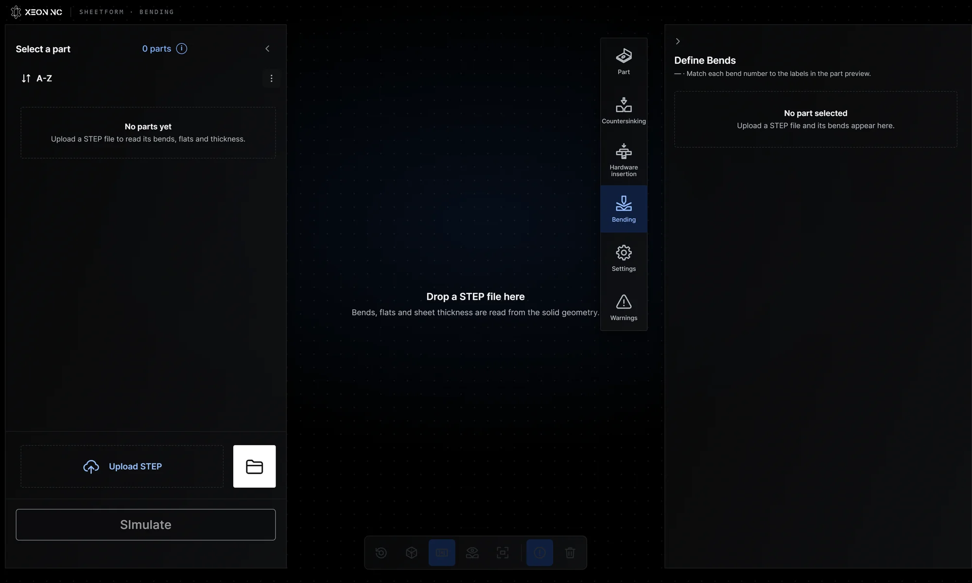
Drop it in. SheetForm reads the solid.
Drag the STEP onto the view or use Upload STEP; add more parts with Upload More. Each part appears in the list with its size, thickness and quantity, and the Part panel shows what was read.
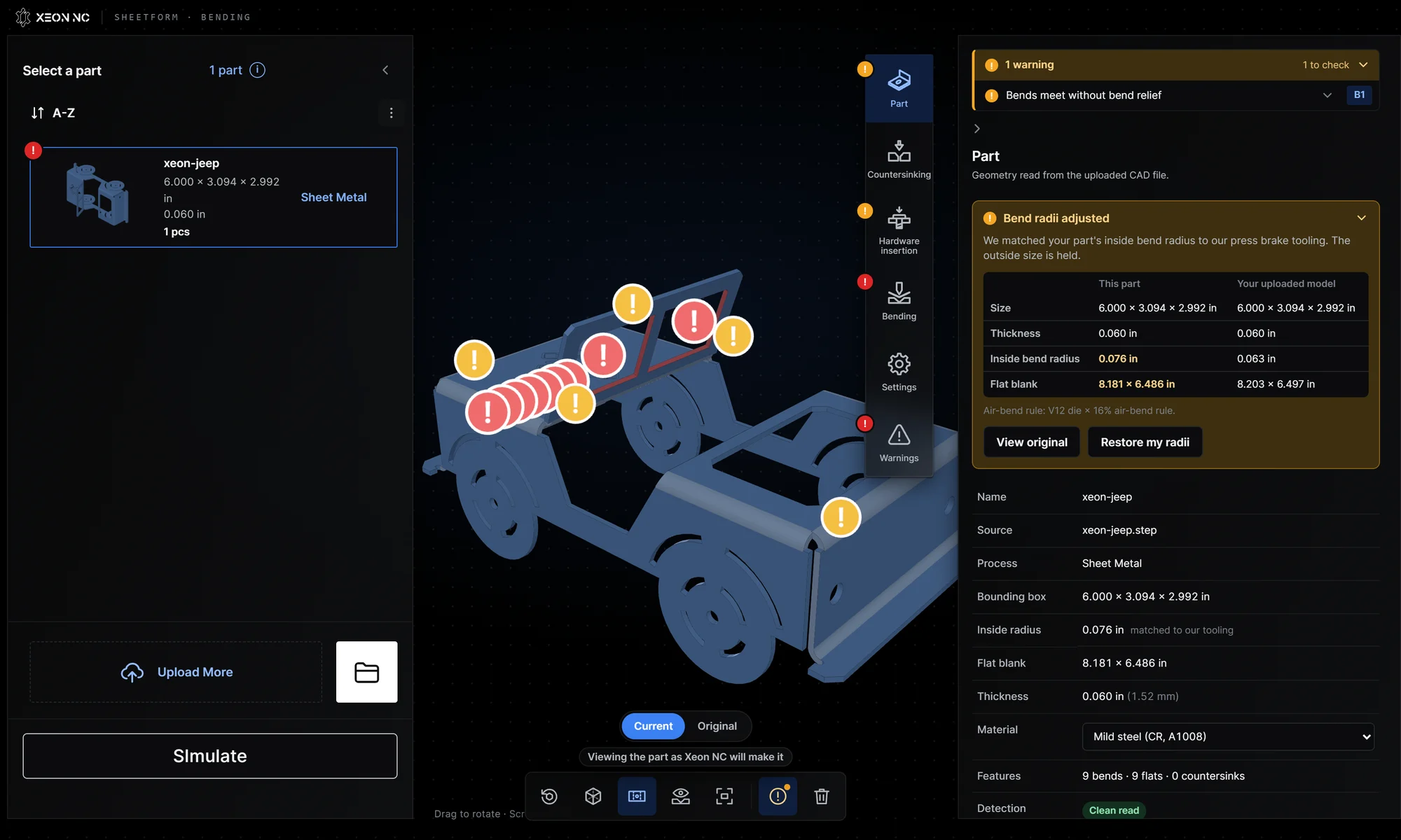
Pick the material
Choose the material in the Part panel. The list shows what we stock at the part's thickness; at 0.060 in that is mild steel (CR, A1008), 304 stainless, 5052 aluminum and galvanized steel. Tooling, bend radii and the simulation all follow from it.
Bend radii matched to our tooling
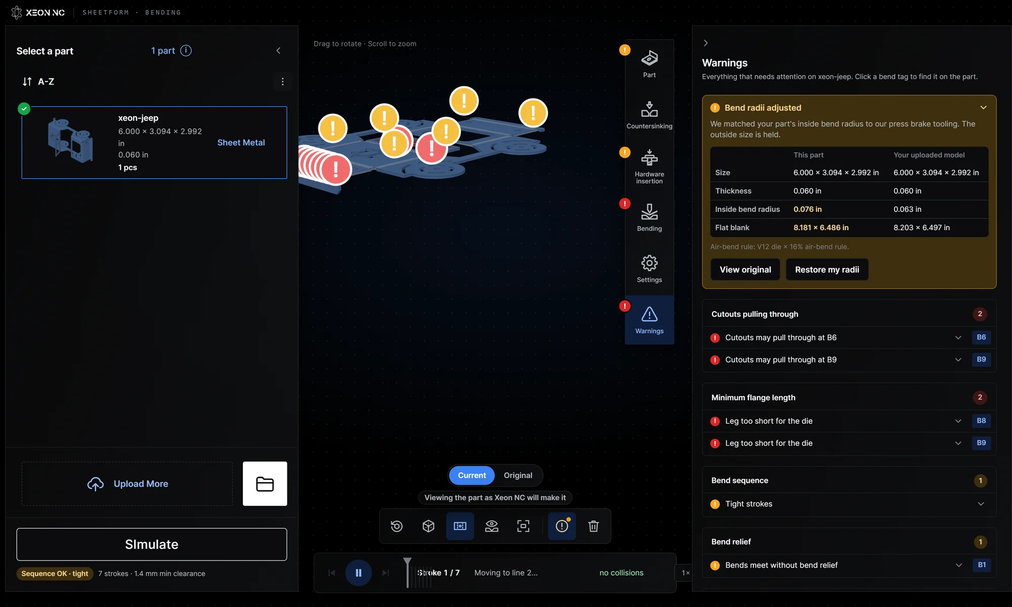
With Match radii on upload on, SheetForm re-forms the part at the inside radius our press brake actually makes, holding the outside size. For the Jeep that moved the inside radius from 0.063 in to 0.076 in (the V12 die × 16% air-bend rule) and the flat blank from 8.203 × 6.497 in to 8.181 × 6.486 in. View original or the Current / Original toggle shows your model as uploaded; Restore my radii puts it back. The K-factor guide explains why the blank changes.
Every bend, its tooling and its force.
The Bending panel lists each bend with its angle, inside radius and direction. Click a bend tag on the part to light it up, and the panel shows the punch, die, stack length and force for that bend line.
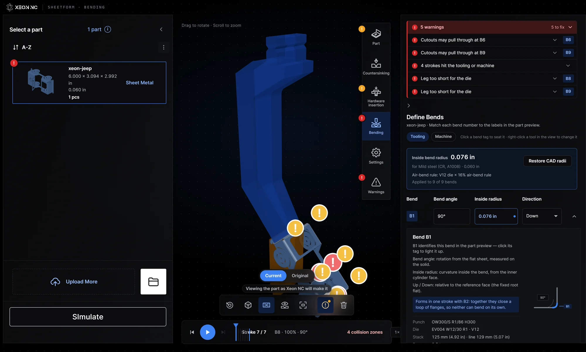
Bend numbers identify features, not the forming order; Simulate plans the order. The Jeep reads as 9 bends on 7 bend lines: B1 and B2 form together, and so do B3 and B4. For each line SheetForm sizes the tool stack to the bend line (125 mm of tooling on the 129 mm line for B1) and estimates the air-bend force.
What SheetForm flags, and why it matters.
Findings appear as badges on the part and in the Warnings panel, grouped by type. Red means fix before ordering; orange means check. Click a bend tag on any finding to jump to it.
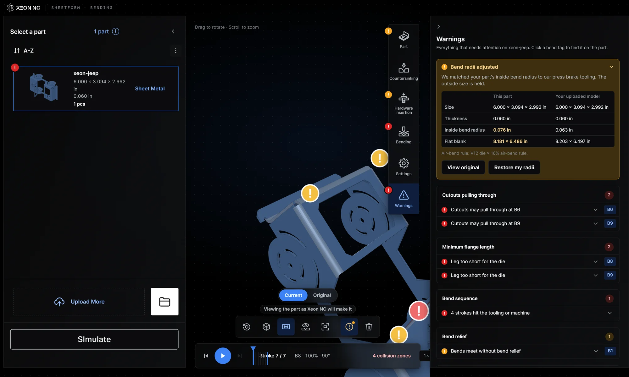
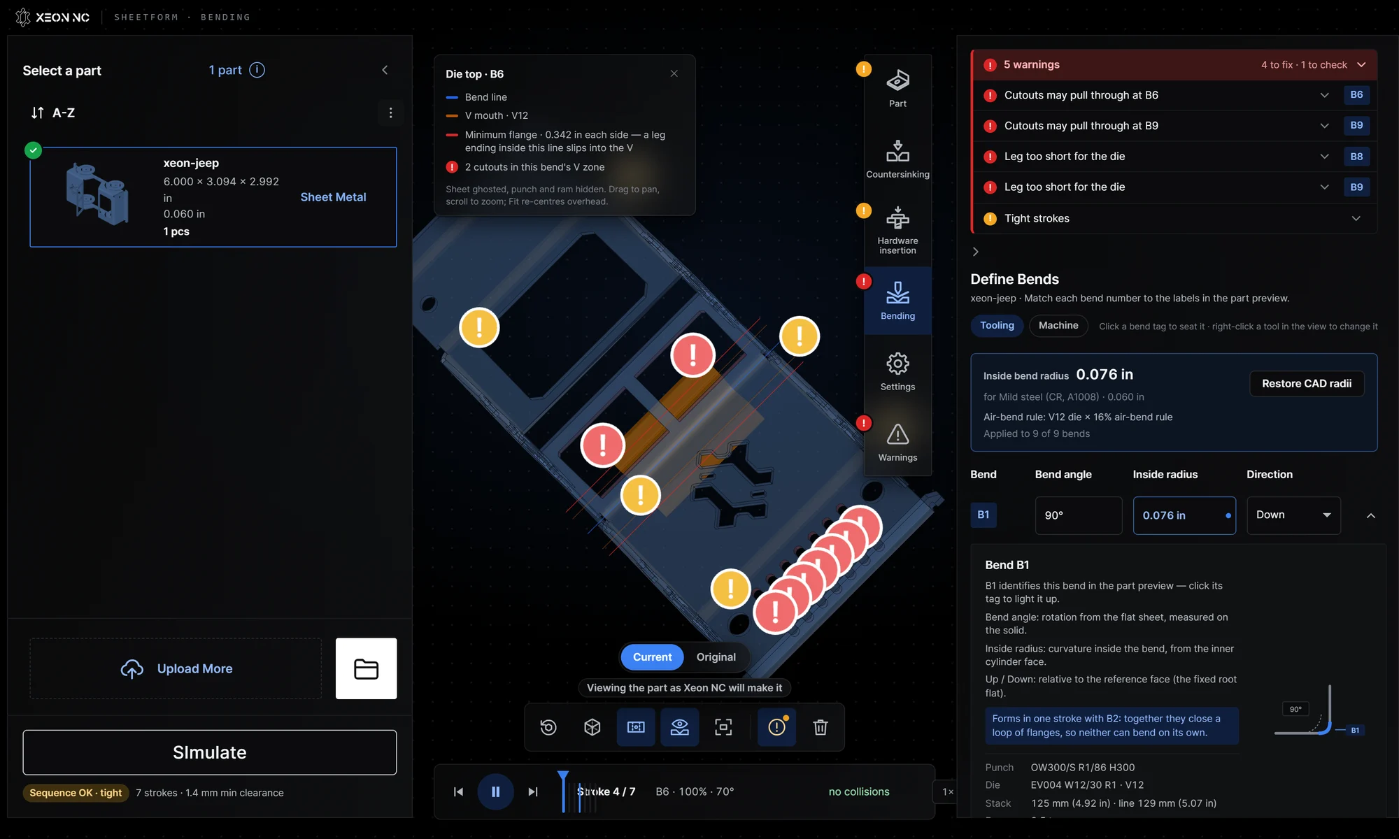
Pull-through: the cutouts at B6 and B9
On the EV004 V12 die, anything within 0.236 in of the bend line sits over the V opening. The Jeep has 2 cutouts in that zone at B6, the closest 0.206 in from the bend line, and 7 at B9, the closest 0.131 in away. As the sheet is pushed into the V, those cutouts stretch out of shape. The fix is to move them further from the bend line, or bend on a narrower die.
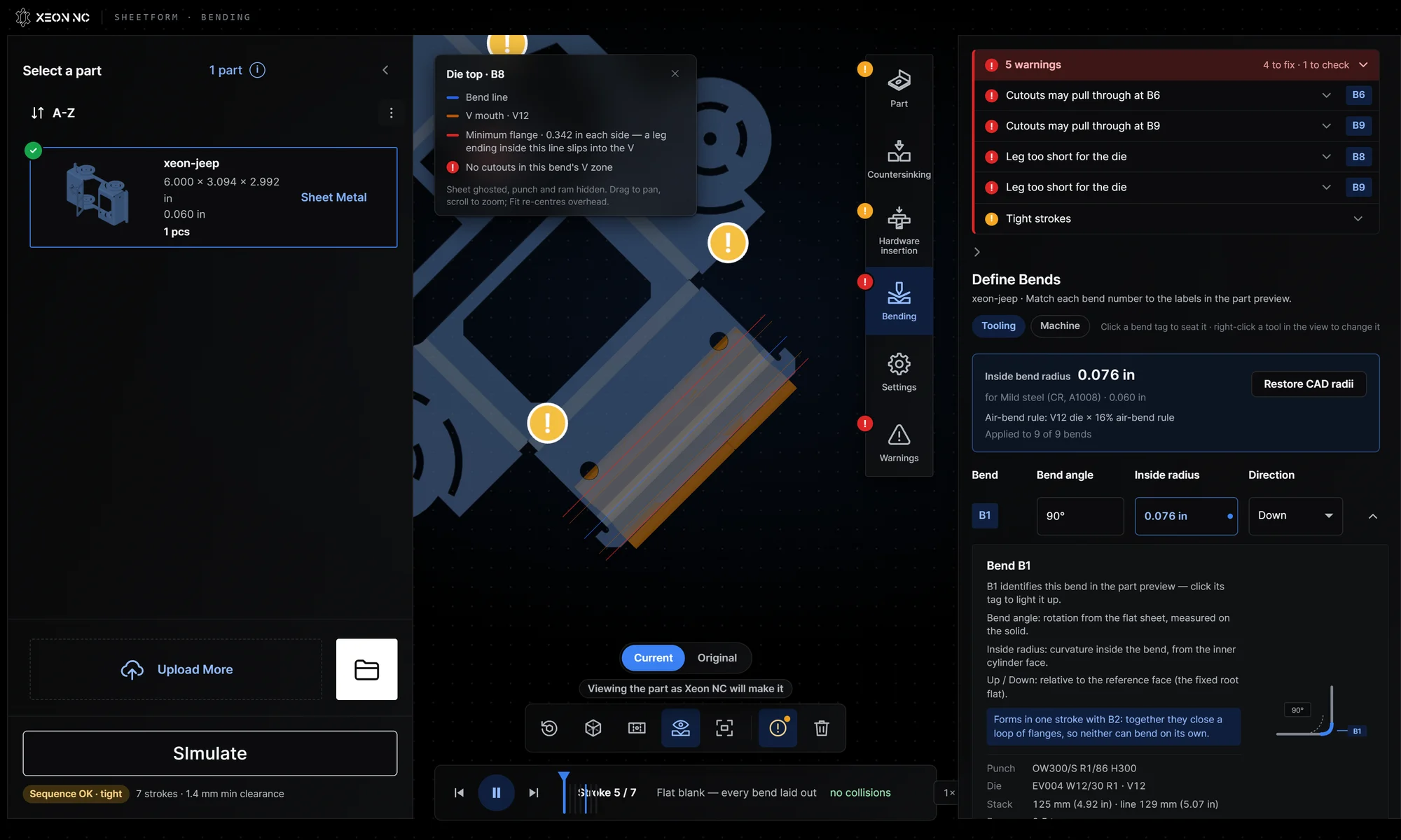
Minimum flange: the legs at B8 and B9
The EV004 V12 die needs 0.342 in of material past each side of the bend to sit on its shoulders. At B8 the shortest leg is 0.306 in and at B9 it is 0.292 in, so those legs slip into the V. Lengthen them to at least 0.342 in, or ask us about a narrower die. The minimum leg length calculator gives the number for any material and thickness.
Related guides go deeper on each check: hole-to-bend distance, bend relief, corner relief, and choosing the inside bend radius.
Let SheetForm find an order that clears.
Before you simulate, the bends run in the order they were read, and on the Jeep 4 strokes hit the tooling or machine. Press Simulate and SheetForm searches for a bend order, feed direction and punch flip that clear, checking each press cycle for collisions.
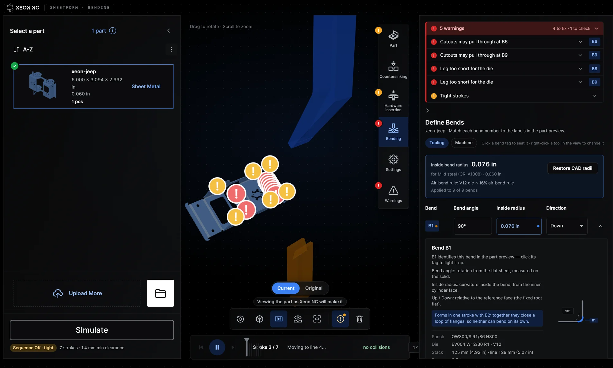
The timeline lists the strokes in order (for the Jeep: B1 + B2, B6, B3 + B4, B5, B7, B9, then B8). Play it, step stroke by stroke, or drag a stroke to reorder it and re-check. Red zones on the timeline mark collisions; scrub to one and click the badge on the part to see exactly where. The view tools switch to the flat pattern, an X-ray of the recognized bends, or the die-top view.
Change the model, then check it again.
SheetForm tells you what to change; the change happens in your CAD. For the Jeep, the list is short:
- Pull-through at B6 and B9. Move the cutouts more than 0.236 in from the bend line, or plan for a narrower die.
- Short legs at B8 and B9. Lengthen both to at least 0.342 in for this die.
- Bend relief at B1. Add a relief notch at least one thickness wide (0.060 in) where the bends meet, or a corner relief hole.
Export a new STEP, drop it into SheetForm again, and Simulate. When the list is clear, upload the part for a quote. For a review by a person, request an engineer-reviewed quote. The earlier SheetForm design review walkthrough covers how we use the same findings with customers.
Know the edges of the tool.
- Hardware is not read from the CAD yet. SheetForm reads bends, flats and countersinks. PEM call-outs are not matched to holes automatically, so check them against the hardware size chart.
- Sheet metal only. It reads formed sheet metal solids. Machined and 3D printed parts are quoted separately.
- Desktop only. Phones and small tablets do not have the memory to run it well.
- Every order is still reviewed. A clean result does not replace the manufacturability review each job gets before production.
Working on a profile you have not modeled yet? The 2D bend simulator lets you sketch a cross-section and check its bends; see the 2D simulator guide.
SheetForm and DFM, answered.
What is instant DFM feedback for sheet metal?
Design for manufacturability (DFM) feedback tells you whether a part can be made as drawn before you order it. SheetForm gives it in seconds: upload a STEP file and it reads every bend, matches the bend radii to the tooling we run, and flags pull-through cutouts, short flanges, missing bend relief and bend sequences that hit the tooling.
Is SheetForm free?
Yes. It runs in your browser with no account. Open SheetForm, drop in a STEP file and the checks run straight away.
Is my STEP file uploaded anywhere?
No. SheetForm reads the solid and simulates the press brake on your own computer; the files you open are not uploaded. When you want a price, upload the part to the instant quote separately.
Which file formats does SheetForm accept?
STEP (.step or .stp) files of formed sheet metal parts. Export a STEP of the bent part from SolidWorks, Onshape, Fusion, Inventor or any CAD system. You can load several parts at once.
What does SheetForm check?
The material and thickness against what we stock, the inside bend radius against our tooling, missing bend relief, countersinks breaking through, cutouts close enough to a bend to pull through on the die, legs too short to sit on the die, flanges meeting each other, and every stroke of the bend sequence against the punch, die and machine. Hardware call-outs are not read from the CAD yet.
Why did SheetForm change my bend radius?
With Match radii on upload turned on, SheetForm re-forms the part at the inside radius our press brake makes for that material and thickness, keeping the outside size. The flat blank changes slightly to match. Your original stays one click away: use View original or Restore my radii.
How is SheetForm different from the 2D bend simulator?
The 2D bend simulator works on a cross-section you sketch. SheetForm reads the full 3D part from your STEP file, so it can check cutouts near bends, closed loops of flanges, the stack length along each bend line and the whole forming sequence in 3D.
Does a clean SheetForm result mean my part will be made exactly as shown?
It means the checks SheetForm runs found nothing to fix. Every order still gets a manufacturability review before production, and tight strokes are verified on the machine.
Clean list? Upload the part.
Pick the material and thickness when you upload. The flat pattern is developed against the die that runs the job.
Get an instant quote →