Understanding CNC Milling
A Xeon NC Engineering Brief
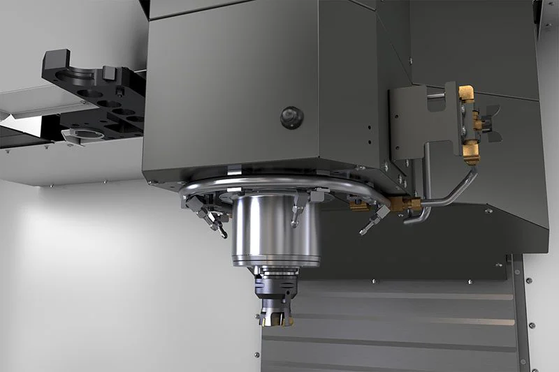
CNC milling is the subtractive manufacturing process behind the most precise machined parts in professional audio, broadcast, and industrial hardware — and understanding it directly influences how well your design survives the transition from CAD to finished part.
Unlike sheet metal operations where a flat blank is cut and bent, milling begins with a solid block of material (billet or bar stock) and removes material until the final geometry emerges. The cutting tool rotates at high speed while the part — held in a fixture or vise — moves through programmed tool paths. The result: complex 3D features, precise holes, slots, bosses, and contoured surfaces impossible to achieve with any other common manufacturing method.
This guide walks through the fundamentals of how CNC milling works, what decisions you as a designer control, and how to get the most out of the process without surprises at the machine.
How CNC milling works
A CNC (Computer Numerical Control) mill is a machine that moves a rotating cutter relative to a workpiece along precisely programmed paths. The operator — or more often a CAM (Computer Aided Manufacturing) software — converts a 3D model into G-code: a sequence of coordinates, feed rates, and spindle speeds that drives every motion the machine makes.
The basic sequence
- Stock selection: Raw billet, plate, or bar stock is chosen slightly oversized relative to the final part envelope.
- Workholding setup: The stock is clamped into a vise, fixture plate, or custom soft jaw. Setup quality directly drives part accuracy.
- Roughing passes: Large cutters remove the bulk of material quickly at higher feeds and depths. Surface finish is not a priority here — speed is.
- Semi-finish & finish passes: Smaller cutters, lighter depths of cut, and slower feed rates bring walls, floors, and radii to final dimension with good surface finish.
- Drilling & tapping: Holes are drilled to size; threads are tapped or helical-milled for blind or through configurations.
- Inspection: Parts are checked on a CMM or with hand gauges against a print or model tolerance.
Axes of motion
The number of axes a machine has determines the complexity of features it can produce in a single setup — and often, the number of setups (flips, re-fixtures) required to finish a part.
Linear motion left-right and front-back. Every milling center has these as the foundational axes driving the part under the spindle.
Vertical motion of the spindle (or table). Controls depth of cut, plunging, and ramping operations into pockets and holes.
Rotation around X, Y, or Z. Present in 4-axis and 5-axis machines. Enables undercuts, angled features, and compound surfaces without re-fixturing.
3-Axis milling
The workhorse configuration. The tool can approach the part from directly above (along Z) and sweep in X and Y. Excellent for flat pockets, slots, drilled holes, and profiles. Any feature that requires a cutter approach from the side or at an angle will require a second setup (re-fixture) or a 4/5-axis machine.
5-Axis milling
Two additional rotary axes allow the spindle to tilt and rotate, reaching undercut geometry, angled walls, and complex compound surfaces in a single setup. Benefits include:
- Fewer setups = better datum-to-datum accuracy across features
- Better surface quality on complex curved surfaces — tool can maintain optimal engagement angle
- Access to undercuts that would otherwise require EDM or manual machining
Tooling & cutters
The cutting tool choice affects achievable geometry, surface finish, material removal rate, and tool life. Designers rarely specify tools, but knowing the common types helps you understand what features are actually feasible and where costs grow.
End Mills (flat, ball, bull-nose)
- Flat end: sharp floor corners, slots, steps
- Ball end: 3D contours, blended radii
- Bull-nose: hybrid — flat floor with corner radius for strength
- Most common cutter in a modern shop
Drill Bits & Spot Drills
- Twist drills for through and blind holes
- Spot drill to start hole precisely
- Center drills for lathe operations
- Tolerances looser than reamed holes
Reamers & Boring Bars
- Reamers finish holes to H7 fit tolerances
- Boring bars: single-point tool for very precise bores
- Use when bearing fits or dowel pin locations are critical
Taps & Thread Mills
- Rigid tapping: fast, requires synchronized spindle & feed
- Thread mills: helical interpolation; safer in hard materials
- Available in standard UNC/UNF and metric pitches
Face Mills & Shell Mills
- Large diameter; rapid facing of flat surfaces
- Achieve very flat, smooth top surfaces quickly
- Common first operation to clean up stock faces
Specialty Cutters
- T-slot cutters for undercut T-slots
- Dovetail mills for dove joints
- Countersink cutters, chamfer mills
- Form tools for custom profiles
Corner radii — the most important design rule
A flat end mill has a circular cross-section. It physically cannot cut a sharp internal corner. Every internal corner on a milled pocket will have a radius equal to (at minimum) the radius of the tool used. Attempting to specify sharp internal corners costs extra: it requires either EDM, a very small end mill (slow, expensive, fragile), or a relief cut (dogbone or tear-drop).
Minimum feature sizes
- Minimum slot width: approximately 0.020″ with a micro-end mill (expensive; prefer ≥ 0.060″)
- Minimum hole diameter: 0.020″ drilled; prefer ≥ 0.060″ for production reliability
- Minimum wall thickness: 0.040″ aluminum; 0.060″ steel (thin walls vibrate during cutting)
Tolerances
Tolerance is the allowable deviation from nominal dimension. In CNC milling, what you can achieve depends on machine capability, fixturing, material, tool deflection, and thermal environment. Specifying tighter tolerances than necessary adds cost without benefit.
| Tolerance class | Typical range | When to use |
|---|---|---|
| Standard | ±0.005″ (±0.127mm) | General features, non-mating surfaces, cosmetic geometry |
| Precision | ±0.002″ (±0.050mm) | Location-critical features, close-clearance assembly |
| Tight | ±0.001″ (±0.025mm) | Bearing journals, dowel pins, slip-fit/press-fit bores |
| Ultra-tight | ±0.0005″ (±0.013mm) | Precision motion stages; typically requires grinding or honing after milling |
| Threaded holes | 6H/6g metric · 2B/2A imperial | Standard free-fit threading; specify class only when fit is critical |
| Reamed holes | H7 (+0.000/+0.001″) | Precision dowel locations, rolling element bearing housings |
Geometric tolerances (GD&T)
When location between features, flatness, perpendicularity, or true position matters more than a simple ± on a dimension, use GD&T controls on your drawing. CNC milling readily achieves:
- Flatness 0.001″ – 0.003″ on a faced surface
- Perpendicularity 0.002″ per inch of height for milled walls
- True position ⌀0.005″ at MMC for drilled hole patterns
- Cylindricity 0.001″ on reamed bores
Material selection for CNC milling
Material choice affects machinability (and therefore cost and lead time), final mechanical properties, and the finishing options available to you. Here are the materials most commonly run in production CNC milling:
Aluminum alloys
The easiest and fastest-machining metals. Excellent strength-to-weight ratio, anodizes well, and holds tight tolerances reliably. Most common grades:
- 6061-T6 General-purpose workhorse. Excellent machinability, good corrosion resistance. Use for enclosures, brackets, structural frames.
- 7075-T6 High-strength aerospace alloy. Harder, holds tolerances extremely well. Higher material cost; used where 6061 isn't stiff enough.
- MIC-6 Cast aluminum tooling plate. Exceptional flatness out of stock; ideal for fixture plates, optical breadboards, reference surfaces.
Steel alloys
Higher strength, wear resistance, and weight. Machinability varies significantly by grade.
- 1018 Low-carbon, free machining, cheap. Good for fixtures and non-critical structural parts. Does not harden well.
- 4140 Chromoly alloy. Strong, tough, good machinability. Used for shafts, gears, die sets. Heat-treatable.
- A2 / D2 Tool steels. Very high hardness after heat treat. Slow to machine; significant tooling wear. Specialty apps only.
Stainless steel
- 303 Best machinability in stainless family. Sulfur addition improves chip breaking. Good for turned/milled parts that don't need to be welded.
- 304 Slightly harder to machine than 303 but more available in plate and bar. Standard food-contact and general corrosion-resistant grade.
- 316 Higher corrosion resistance; harder to machine. Specify when chloride or marine exposure is a concern.
Engineering plastics
- Delrin (POM) Low friction, dimensionally stable, easy to machine. Great for gears, sliding parts, bushings.
- PEEK High-temp, chemical-resistant engineering plastic. Expensive; used when metal is too heavy or conductive.
- UHMW Ultra-high-molecular-weight polyethylene. Very low friction, impact-resistant. Slides, wear strips, impact surfaces.
Design for milling
Good milling designs are not just geometrically correct — they're manufacturable without excessive cost, setup count, and fragile tool paths. These rules apply regardless of which shop you work with.
1. Eliminate unnecessary sharp internal corners
Already covered under tooling — but worth repeating as rule #1. Specify corner radii ≥ 130% of the smallest end mill that enters the pocket. Show them on your model and drawing.
2. Respect aspect ratios in pockets and walls
Deep narrow pockets require long, slender end mills — which deflect. As a guideline:
- Pocket depth should not exceed 4× the pocket width for aluminum
- Pocket depth should not exceed 2–3× the pocket width for steel or stainless
- Thin walls (below 0.040″ in aluminum) vibrate during machining and become impossible to hold to tolerance
3. Minimize the number of setups
Every time a part is unclamped, rotated, and re-clamped, a new datum is introduced. This is one of the top contributors to multi-face positional error. Design your part so that all critical features are accessible in as few orientations as possible:
- Locate all important holes on the same face when possible
- Avoid features on the bottom face that require access before primary machining
- Include datum bosses or dowel pin holes to ensure accurate re-location if two setups are unavoidable
4. Add machining stock to thin sections
If your part has a very thin section adjacent to a heavily machined area, the machining stresses may bow the part. Add temporary stock in that area (noted on the drawing) to be removed in a last, lightly-loaded finishing operation.
5. Thread specifications
Always call out thread diameter, pitch, class of fit, and whether through or blind. For blind threaded holes, specify minimum full thread depth separately from minimum hole depth. Leave at least 1.5× thread diameter of extra hole depth beyond full thread for the tap to bottom out safely.
M6 × 1.0 — 6H, 12mm FULL THREAD MIN
HOLE DEPTH: 16mm MIN
EXAMPLE INCORRECT:
"M6 threaded hole, 12 deep" ← no pitch, no class, no thread vs. hole depth separation
6. Avoid undercutting where possible
Undercuts — features not accessible from the Z (top) direction — require either a 5-axis machine, a specialty undercut end mill (T-slot, lollipop), or an extra setup. All of these add cost. If the undercut is purely cosmetic, ask if a chamfer or stepped geometry achieves the same result.
Surface finish
Milled surfaces have a characteristic scallop pattern from the rotating cutter. The roughness is quantified as Ra (arithmetic average roughness). Finish quality is traded against cycle time — achieving a finer finish means lighter cuts, slower feeds, and more passes.
| Finish level | Ra value | Appearance | Typical use |
|---|---|---|---|
| As-milled (rough) | 125–250 µin | Visible cutter marks, toolpath lines | Non-cosmetic internal features, stock relief |
| Standard milled | 63–125 µin | Light finish marks; typical shop result | Most external faces, brackets, enclosures |
| Fine milled | 32–63 µin | Smooth, minimal marks | Mating faces, gasket surfaces, anodize prep |
| Bead blasted | 32–64 µin | Uniform matte texture; hides tooling marks | Cosmetic aluminum, pre-anodize |
| Ground | 8–16 µin | Very smooth, near-mirror on steel | Precision reference surfaces, bearing seats |
Anodizing and coatings
Milled aluminum parts are typically bead blasted and then anodized for corrosion protection, wear resistance, or color. Important considerations:
- Type II anodize adds 0.0002″ – 0.0004″ per side. Account for this in any precision bore or press-fit dimension.
- Type III (hardcoat) adds up to 0.001″ per side. Tight holes must be machined undersized to compensate.
- All sharp edges should be broken (0.010″ – 0.020″ chamfer) before anodizing to prevent coating burn-through at corners.
CAD & file preparation
Providing clean, complete files is the single fastest way to reduce quoting time and avoid manufacturing holds. Here's what to check before uploading:
Accepted formats
- .STEP Preferred for all machined parts — preserves solid geometry faithfully across all CAM systems
- .IGES Acceptable; verify surface normals and check for gaps
- .SLDPRT Native SolidWorks accepted with full feature tree
Model checklist
- All threaded holes modeled as plain holes (no thread helix in solid model) — call out thread spec on the drawing only
- All corner radii present and dimensioned — don't leave sharp internal corners with the expectation the machinist will guess the radius
- Final part envelope is the finished part — do not include extra machining stock in the model unless it is a castings/forging baseline file
- Model units confirmed (inches vs. mm) and stated in your order notes
- Any features requiring tight tolerance called out in an accompanying PDF print or model-based definition (MBD)
Drawing best practices
Even in a model-based workflow, a 2D PDF drawing eliminates ambiguity and creates a legal document of record. Include at minimum:
- Title block with part number, revision, date, and drawn-by
- General tolerance block (e.g., .XXX ±.005, .XX ±.010, angles ±0.5°)
- Material specification with alloy and temper (e.g., Aluminum 6061-T6 per AMS-QQ-A-200/8)
- Finish specification and any masking notes (masked from anodize, keep bare, etc.)
- Critical dimensions with explicit tolerances called out